TP-6745 7/1064 Section 3 Controller Test and Replacement
If the generator set engine does not start, check the
engine start connections to the generator set. Verify that
the generator set master switch is in the AUTO position.
Troubleshoot the generator set if the engine start
connections are good but the engine does not start.
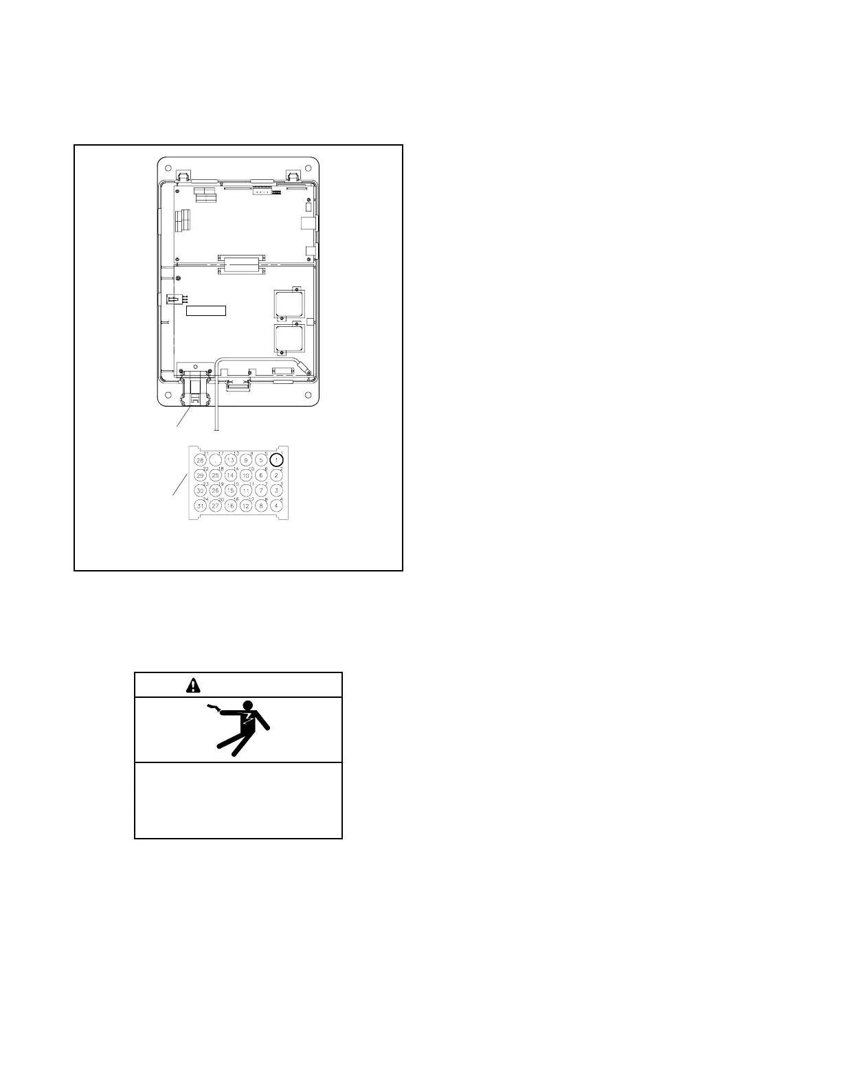
1. Transfer switch harness connection, P1
2. Connector J1 pin numbering
1
GM46733
J1
2
Figure 3-18 Transfer Switch Harness-to-Controller
Connection
3.10 Controller DIP Switches
Hazardous voltage.
Will cause severe injury or death.
Disconnect all power sources before
opening the enclosure.
DANGER
Two DIP switches on the main logic board are assigned
functions. Switches 3 and 4 are not used. The DIP
switches are located on the controller’s main logic board
on the inside of the enclosure door. Figure 3-19 shows
the locations of the switches on the controller circuit
board. It is not necessary to remove the logic assembly
cover to see or adjust the DIP switches.
SW1-1, Password Disable. Closing the password
disable DIP switch SW1-1 disables the setup password
and resets it to the factory defaults. When the switch is
closed, system setup and programming is allowed
without the need to enter a password.
Note: Disable the setup password only during service
unless the transfer switch is installed in a secure
location.
Closing and then reopening DIP switch SW1-1 resets
the password to the default value, 0000.
The test password is not affected by this DIP switch.
Use the Reset Data screen to disable the test password.
SW1-2, Maintenance. The maintenance DIP switch
inhibits transfer during ATS service. When this switch is
in the closed position, power switching device functions
are disabled. The Not in Auto LED flashes red and the
message Maintenance Mode is indicated on the LCD
screen. In addition, a programmable digital output is
turned on and an entry in the event log indicates that the
maintenance mode has been activated. System
monitoring and setup are allowed while in maintenance
mode.
Close and lock the enclosure door before energizing the
transfer switch.