TP-6745 7/1066 Section 3 Controller Test and Replacement
3.12 Position Microswitch Test
Disconnect power to the transfer switch and use an
ohmmeter or test lamp to check the operation of the
position microswitches. Manually operate the switch
and check for continuity across pins 10 and 13 of the
connector P1 for Source E and pins 10 and 14 for
Source N.
3.13 Programmed-Transition
Interface Board
ICCB models use the programmed-transition interface
board.
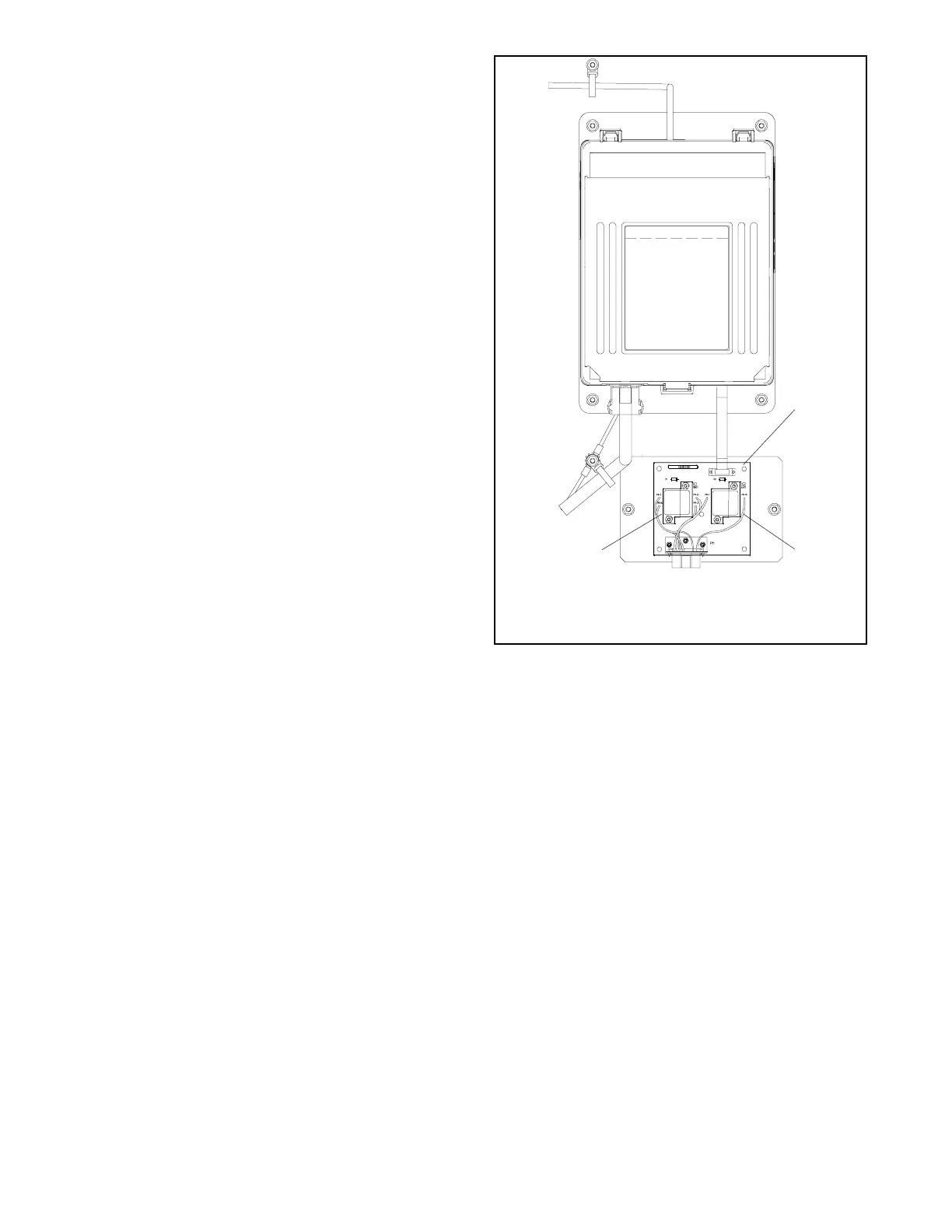
The programmed-transition interface board (PTIB)
contains two replaceable 10-amp relays, K1 (NR1) and
K2 (ER1). See Figure 3-21. Refer to the operation
diagrams in Section 3.5 and to the schematic diagram
provided with the transfer switch to troubleshoot the
relays.
2
tp6158
1. Programmed-Transition Interface Board (PTIB)
2. K2 (ER1) Relay
3. K1 (NR1) Relay
1
3
Figure 3-21 Programmed-Transition Interface Board

 Loading...

