TP-6745 7/10 73Section 4 ICCB Power Switching Device Diagrams
Section 4 ICCB Power Switching Device Diagrams
RESET
12
11
9
8
7
6
10
19
18
17
16
15
1
2
3
4
5
14
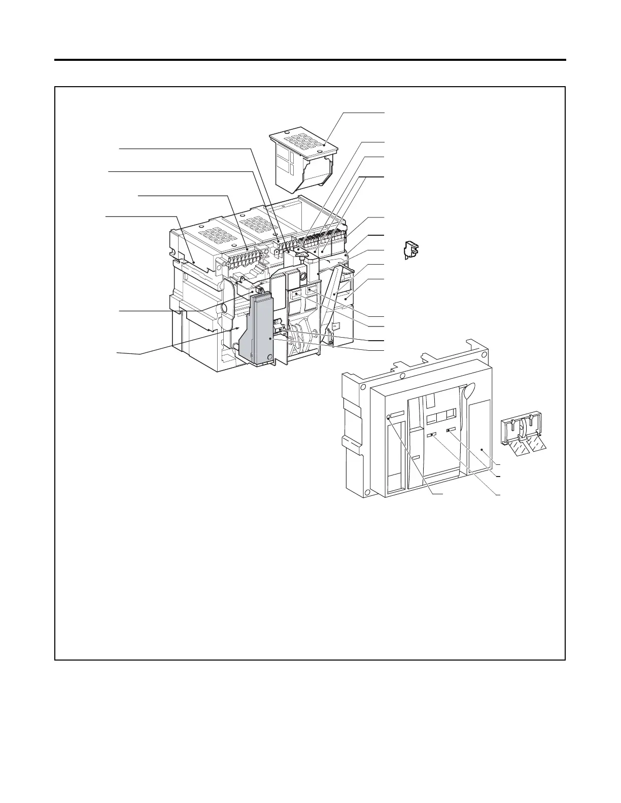
1. Arc chamber
2. Shunt trip (MX1)
3. Auxiliary contact connection
4. Two (2) blocks of four additional switches (OF) or combined
connected/closed switches (EF)
5. Block of four form C auxiliary contacts (OF)
6. Shunt close (XF)
7. Ready to close contact (PF)
8. Charging handle
9. Spring charging motor (MCH)
10. Closing pushbutton
11. Opening pushbutton
12. Operation counter
13. Trip unit
14. Overcurrent Trip Switch (SDE1)
15. Overcurrent trip switch (SDE2) or electric reset
16. Lifting tab
17. Trip unit connection to overcurrent trip switch
18. Auxiliary control connection
19. Shunt trip (MX2) or undervoltage trip device (MN)
20. Open/close pushbutton cover (lockable with padlock
21. Faceplate
22. Charged/discharged indicator
23. Open/close indicator
24. Push to reset on fault trip
13
20
21
22
2324
tp6738
Figure 4-1 ICCB Power Switching Device