TP-6745 7/1028 Section 2 Troubleshooting
2.8 Warnings and Faults
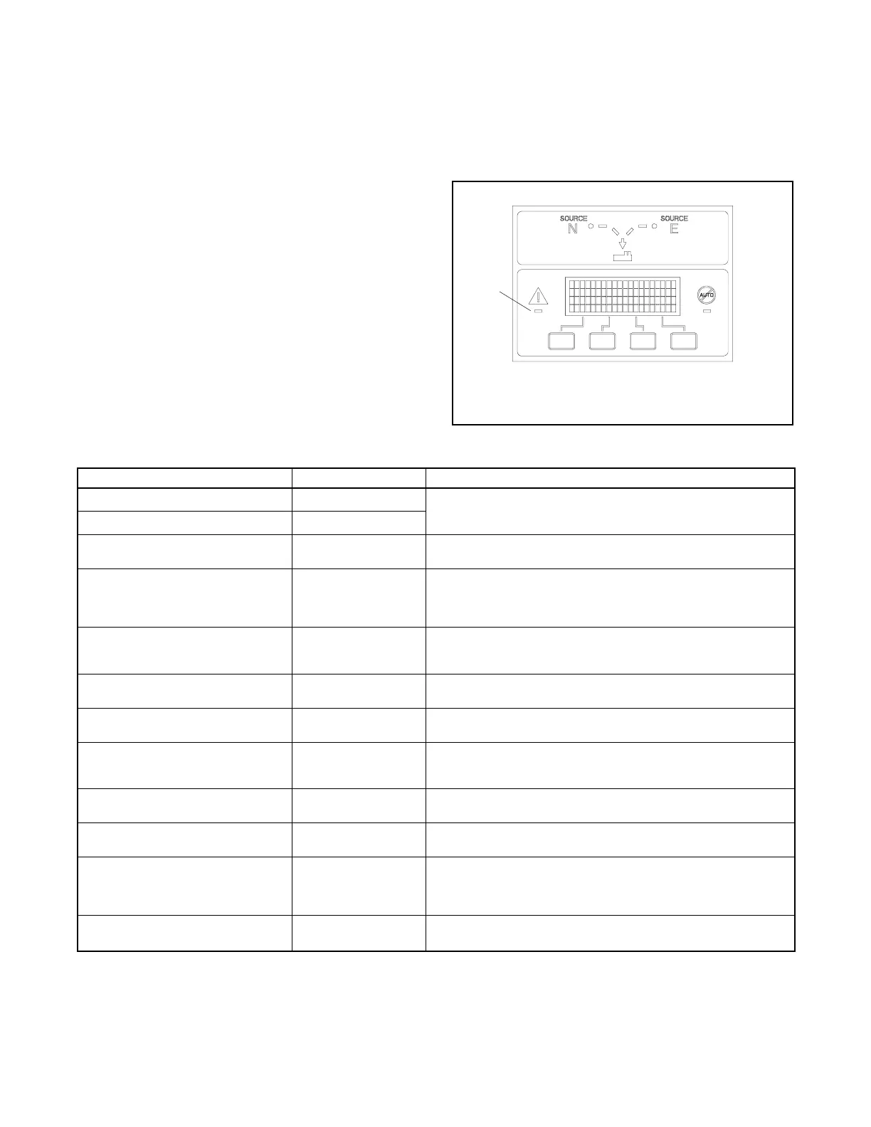
When a fault exists, the System Alert indicator lights, a
designated output and the common fault output are
turned on, and an appropriate message is displayed to
indicate the fault. See Figure 2-12 for the location of the
System Alert indicator.
ATS warnings and faults are shown in Figure 2-13.
There are three types of warning/fault conditions:
Warning. Warnings automatically reset with a source
availability change or a transfer request.
Fault Requiring Manual Reset. Under these
conditions, normal ATS operation is halted. Active
modes are turned off. If the c ontactor is in the preferred
source position, the engine cooldown time delay
executes and the engine start contacts open, allowing
the generator set to shut down. See Section 2.8.1 for
instructions to reset faults.
Self Resetting Faults. Under these conditions, active
modes are turned off. If the c ontactor is in the preferred
source position, the engine cooldown time delay
executes and the engine start contacts open, allowing
the generator set to shut down. When the fault condition
is corrected, the fault is automatically cleared from the
controller and normal ATS operation continues.
See Section 2.9 for troubleshooting recommendations.
GM46892
1. System Alert LED
1
Figure 2-12 Fault Indication
Condition Type Description
Failure to Acquire Standby Source Warning The source voltage did not reach the acceptable range within a
set time (see Time Delays). For example, the standby source
generator set did not start.
Failure to Acquire Preferred Source Warning
External Battery Low Warning The voltage of the battery connected to the external battery
supply module (EBSM) is low.
Failure to Transfer Warning The signal to transfer is sent to the contactor and the main
shaft auxiliary switch fails to indicate a complete ATS position
change. The controller will attempt to transfer the unit three
times before the fault is indicated.
Auxiliary Switch Fault Manual Reset Fault The main shaft auxiliary switches indicate that the ATS is in
more than one position, or the position changed when no signal
was sent to initiate the change.
Auxiliary Switch Open Manual Reset Fault The main shaft auxiliary switches indicate that the ATS is in
neither position (all inputs are open).
SrcN(orSrcE)RotationErr Self-Resetting Fault The detected phase rotation of one or both sources does not
match the preselected setting.
I/O Module Lost Comm Self-Resetting Fault An I/O device has stopped communicating or does not have a
correct address specified. Fault resets if communication is
reestablished.
Module Status Change Self-Resetting Fault An accessory module has been disconnected OR a new
module is detected. See Section 2.8.2 to reset.
Module Status Conflict Self-Resetting Fault An accessory module has been replaced with a different type
of module. See Section 2.8.3 to correct.
Source1/Source2 Breaker Trip
(service entrance models only)
Manual Reset Fault The Source1 or Source2 circuit breaker in the service entrance
transfer switch has tripped due to an overcurrent condition.
Identify and correct the cause of the fault before resetting the
controller.
External Fault
(Remote Common Alarm)
Self-Resetting Fault The input contact assigned to the remote common alarm input
function is closed.
Figure 2-13 Warnings and Faults