TP-6745 7/10 23Section 2 Troubleshooting
2.4 System Power
2.4.1 Verify Power to ATS
If the transfer switch display is off, check for power to the
transfer switch. If the utility source is not available,
check for emergency power. Follow the voltage check
procedure in Section 2.4.2, Voltage, Frequency, and
Phase Rotation Checks, to check voltage at the Source
N (normal) or Source E (emergency) lugs.
If utility power is not available and the emergency
generator set is not running, check that the generator
set master switch is in the AUTO position. Verify that the
generator set runs when the master switch is moved to
the RUN position. If the engine does not start,
troubleshoot the generator set as described in the
generator set documentation. Otherwise, check the
engine start circuit. See Section 3.9.
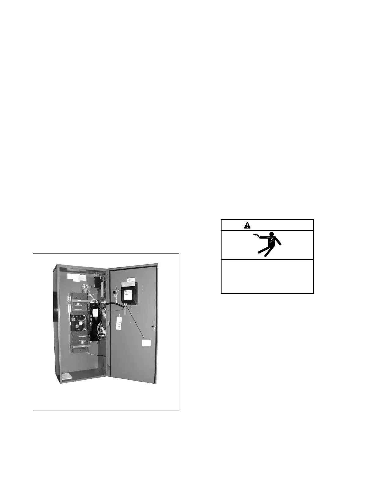
If the utility source is available but the transfer switch
display is off, verify that the transfer switch wiring
harness is connected to the controller. See Figure 2-4.
Note: Perform the service disconnect and control circuit
isolation procedures before disconnecting or
reconnecting the controller harness. See
Sections 1.6 and 1.7 for instructions.
An LED on the controller power board lights to indicate
power to the board. See Figure 3-5.
1200SE
1. Transfer switch harness connection to controls,
controller connector P1
1
Figure 2-4 Transfer Switch Harness Connection to
Control Board, Typical
2.4.2 Source Voltage, Frequency, and
Phase Rotation Checks
The voltage, frequency, and phasing of the transfer
switch and the power sources must be the same to avoid
damage to loads and the transfer switch. Compare the
voltage and frequency ratings of the utility source,
transfer switch, and generator set, and verify that the
ratings are all the same.
Read and understand all instructions on installation
drawings and labels on the switch. Note any optional
accessories that have been furnished with the switch
and review their operation.
Note: Source N is the source connected to the normal
side of the transfer switch. Source E is the source
connected to the emergency side of the transfer
switch.
The voltage check procedure requires the following
equipment:
D A digital voltmeter (DVM) with electrically insulated
probes capable of measuring the rated voltage and
frequency
D A phase rotation meter
Hazardous voltage.
Will cause severe injury or death.
Only authorized personnel should
open the enclosure.
DANGER
Testing live electrical circuits. Hazardous voltage or
current can cause severe injury or death. Have trained and
qualified personnel take diagnostic measurements of live
circuits. Use adequately rated test equipment with electrically
insulated probes and follow the instructions of the test
equipment manufacturer when performing voltage tests.
Observe the following precautions when performing voltage
tests: (1) Remove all jewelry. (2) Stand on a dry, approved
electrically insulated mat. (3) Do not touch the enclosure or
components inside the enclosure. (4) Be prepared for the
system to operate automatically.
(600 volts and under)