TP-6745 7/1022 Section 2 Troubleshooting
From the main screen, step to View Event History and
display recent events as shown in Figure 2-1. Possible
event descriptions are listed in Figure 2-2.
If a fault condition or alarm is displayed, proceed to
Section 2.9.
System Ready
LD Exer ##/## @ ##:##
Norm ###V Emer ###V
B View Set Test
View
Event History
BY"Main
Press the right arrow
button to view events.
Main Screen. Press
the View button to step
to the Event History
screen.
B Back
Event Description
ON / OFF MM/DD/YY HH:MM
Additional Info
Press the down arrow
button to step through
events.
Figure 2-1 Viewing Event History
Event Descriptions
End Time Delay Btn Low Battery Voltage
Test Btn Remote Common Alarm
Exercise Btn Bypass Contactor Dis
Lamp Test 3 Src System Disable
Service Req’d Reset Over Frequency
Maint DIP Switch Under Frequency
Pwd DIP Switch Phase Loss
Manual Option Switch Phase Rotation Error
New Module Over Voltage L1--L2
Contactor in Off Over Voltage L2--L3
Contactor in Src N Over Voltage L3--L1
Contactor in Src E Under Voltage L1--L2
Low Battery Under Voltage L2--L3
Exerciser Active Under Voltage L3--L1
Fail to Acquire Pref Voltage Imbalance
Fail to Acquire Stby Save History To File
Fail to Transfer Auto Loaded Test End
I/O Module Lost Comm Test Loaded Changed
Aux Switch Fault Pref Source Changed
Aux Switch Open Reload Dflt Params
Battery Backup Low MODBUS Peak Shave
Rem End Time Delay MODBUS Forced to OFF
Forced Trans to Off MODBUS System Test
Peak Shave Mode Battery Control Out
Inhibit Transfer USB Connected
Remote Test USB Disconnected
Figure 2-2 Events
2.3 Data Log Files
The data log files listed in this section are available on
MPACt 1500 controllers with version 2.0.0 or later
application code. The data log files can be viewed using
spreadsheet software and used to help troubleshoot
ATS operation problems.
Data log files are generated by the MPAC 1500
controller as described below. See TP-6714, MPACt
1500 Operation Manual, for detailed instructions to
create the following data files.
USB Data Logger
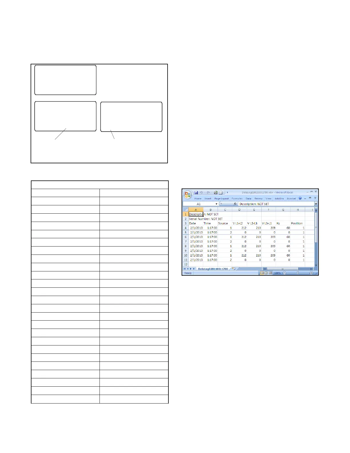
Use the USB Data Logger function in the MPAC 1500
controller’s Set System menu to create a DataLog file.
The file contains time- and date-stamped readings of
voltage, frequency, and contactor position (source 1 or
2). Data log files have the form
DataLogYYMMDDHHMMSS.csv where YYMMDD is
the date (year/month/day), and HHMMSS is the time
that the file was created in hours:minute:seconds.
Figure 2-3 shows a sample file.
Figure 2-3 Sample Data Log File
MinMax Files
Use the MinMax function, which is found in the MPAC
1500 controller’s Set System menu under USB Data
Logger, to create a MinMax.csv file. The file contains
minimum and maximum readings of voltage and current
supplied to the load over a selected time period. The
MinMax file is overwritten each time the MinMax
operation is performed.