TP-6745 7/10 65Section 3 Controller Test and Replacement
GM46733
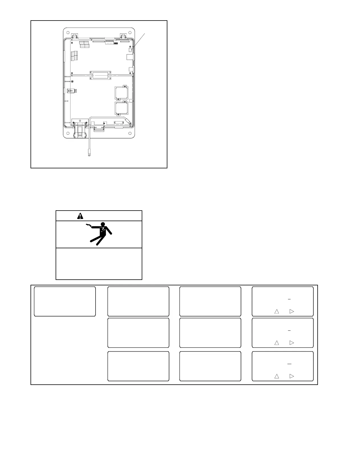
1. DIP switches SW1
1
Main Logic
Board
Power
Board
Figure 3-19 DIP Switch Location (cover removed for
illustration only)
3.11 Calibration
Hazardous voltage.
Will cause severe injury or death.
Only authorized personnel should
open the enclosure.
DANGER
Testing live electrical circuits. Hazardous voltage or
current can cause severe injury or death. Have trained and
qualified personnel take diagnostic measurements of live
circuits. Use adequately rated test equipment with electrically
insulated probes and follow the instructions of the test
equipment manufacturer when performing voltage tests.
Observe the following precautions when performing voltage
tests: (1) Remove all jewelry. (2) Stand on a dry, approved
electrically insulated mat. (3) Do not touch the enclosure or
components inside the enclosure. (4) Be prepared for the
system to operate automatically.
(600 volts and under)
The transfer switch controls are calibrated at the factory
and should not require recalibration in the field.
However, if recalibration is necessary, measure the
source voltages as instructed in Section 2.4.2, record
the measured values, and use the Setup Screen-
Calibration to enter the measured values. See
Figure 3-20.
The current sensing accessory is required in order for
the transfer switch to measure and display the current
values. Use a clamp-on current sensing meter to
measure the current and enter the measured values
through the Setup Screen--Calibration shown below.
Calibrate
L - N Voltages
Source N(E)
BY"Back
Back Save
L1 - L0 VAC ###
Cal VAC ?
??
Calibration
BY"Main
Calibrate
L - L Voltages
Source N(E)
BY"Back
Back Save
L1 - L2 VAC ###
Cal VAC ?
??
Calibrate
L1 - L2 Voltage
BY"Back
Calibrate
L1 - L0 Voltage
BY"Back
Calibrate
Load Current
BY"Back
Back Save
LA Amps ####
Cal Amps ?
???
Calibrate
LA Current
BY"Back
Figure 3-20 Calibration