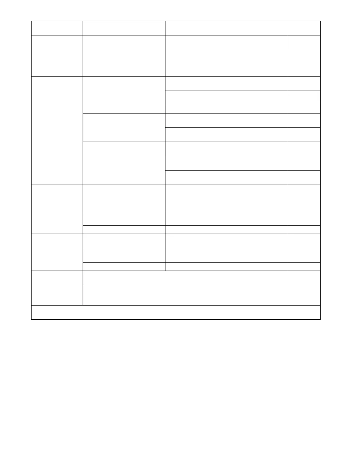
TP-6745 7/1036 Section 2 Troubleshooting
Problem
See
Section
CheckPossible Cause
Transfer to
generator source
without a power
failure in the utility
source
Loaded test or exercise sequence
is active.
Check the controller display for indication that a
test or exercise sequence is active.
O/M
Utility power switching device has
tripped due to an over current
condition.
Identify and correct the cause of the tripped circuit
breaker before resetting the fault on the controller.
See the ATS Operation/Installation manual for
overcurrent trip information and reset instructions.
ATS O/I/M
No LEDs illuminated No power to the transfer switch
Check that source switches or circuit breakers are
closed.
—
Verify that at least one source is available. Check
for utility or gen set voltage to the ATS.
2.4.2
Check source connections. W/D
No power to the controller
Check that the transfer switch harness is
connected to the controller.
Figure 2-4
Check the harness for loose connections or broken
leads (continuity check).
W/D
One or more faulty LEDs
Press the Lamp Test button to check the operation
of all LEDs.
3.1.3
If no LEDs light during the lamp test, troubleshoot
power and connections to the controller.
3.3
Replace the controller if one or more LEDs do not
light during the lamp test.
3.16
Source available
LED off when
Source is available
Malfunctioning LED Press the Lamp Test button to check the operation
of all LEDs. Replace the controller if one or more
LEDs do not light. If no LEDs light, troubleshoot
power and connections to the controller.
3.1.3
Source settings do not match
actual source parameters
Check settings. 2.5
Incorrect ATS meter calibration Check calibration. 3.11
Position LED not lit
Position microswitch malfunction Check the operation of the position microswitches. 3.12
Transfer switch in intermediate
position
Manually operate the transfer switch and check the
position LED operation.
TOC
LEDs not functioning See No LEDs illuminated in this table. —
Controller display is
blank
See Figure 2-20, Blank Display Troubleshooting. 2.11
Strange characters
on controller display
or controller lockup
See Figure 2-23, Troubleshooting Display Errors or Controller Lockup. 2.11
O/I/M= Operation and Installation Manual; O/M = Operation Manual; TOC = Table of Contents, this manual;
W/D = Wiring Diagrams