TP-6745 7/10 71Section 3 Controller Test and Replacement
15. To replace the entire controller assembly:
a. Support the controller assembly and remove
four nuts at the corners.
b. Carefully remove the entire controller
assembly, including the user interface panel,
which is part of the assembly.
c. Replace the entire assembly with a new
controller. Secure the four nuts at the corners
and tighten them to no more than 6.8 Nm
(5 ft. lb. or 60 in. lb.) torque.
d. Proceed to step 18.
16. To replace the logic circuit board:
a. Disconnect the ribbon cable connecting the two
circuit boards.
b. Disconnect the ribbon cables to the user
interface at connectors P14 and P17.
c. Remove the four mounting screws near the
corners of the board and pull the circuit board
straight off the carrier.
d. Set the new circuit board in place and secure
with four mounting screws.
e. Reconnect the ribbon cables.
f. Proceed to step 18.
17. To replace the power board:
a. Disconnect the ribbon cable connecting the two
circuit boards.
b. Remove the three mounting screws plus the P1
connector bracket screws and four screws
securing the power relays must be removed.
c. Set the new power board and insulating cover
in place. Install the mounting screws, making
sure to reinstall the ground lead and the P1
connector with mounting bracket.
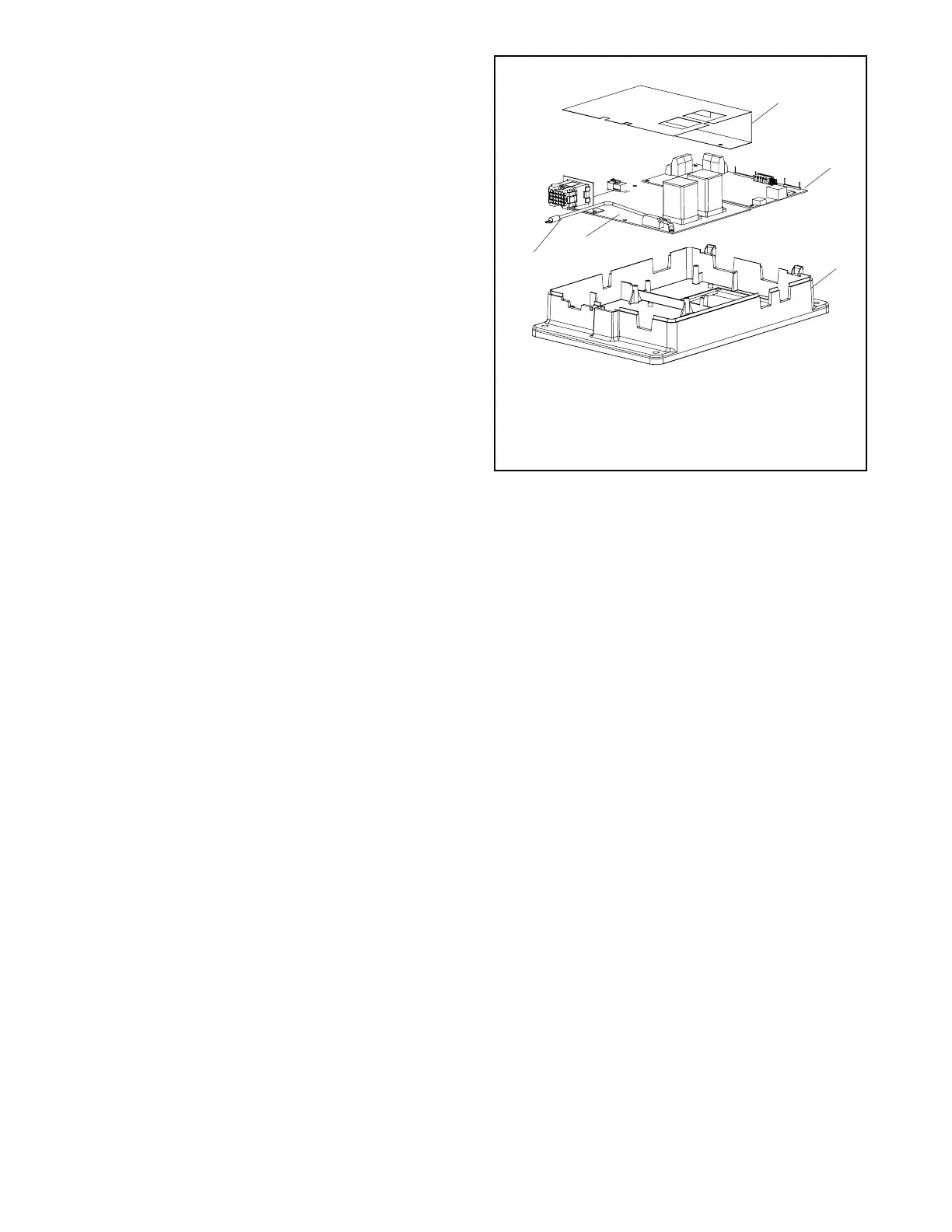
Note: Be sure to reinstall the insulating cover for
the power board. See Figure 3-25.
d. Reconnect the ribbon cable between the
boards.
e. Proceed to step 18.
1
GM46733
1. Insulator, power board
2. Logic board
3. Carrier
4. Power board
5. Ground lead
2
3
4
5
Figure 3-25 Controller Circuit Board Assembly
Reconnect the controller assembly.
18. Connect the controller ground wire to the terminal
on the enclosure door. See Figure 3-5.
19. Connect the programmed-transition board, if
equipped, to the controller at connector P2. See
Figure 3-5.
20. Connect the I/O leads to logic board terminal strip
TB1, using the labels attached in step 11 to connect
the leads to the appropriate terminals. See
Figure 3-5.
21. Connect RS-485 communication cable, if used, to
logic board terminal strip TB2, using the labels
attached in step 12 to connect the leads to the
appropriate terminals. See Figure 3-5.
22. Connect the accessory module assembly (if
equipped) at connector P16.
23. Reconnect any other items that were disconnected
from the controller. See Figure 3-5 for connector
identification.
24. Connect the transfer switch harness to the
connector on bottom of the controller.
 Loading...


