11. EXPLANATION OF COMPONENTS
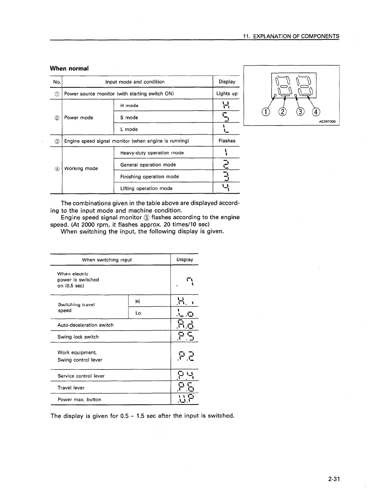
When normal
No.
input mode and condition
Power source monitor (with starting switch ON)
H mode
Display
Lights up
1-I
\ \
Power mode
S mode
r
5
AE097380
\
1 L mode
I i
Engine speed signal monitor (when engine is running)
Flashes
Heavy-duty operation mode
I :
Working mode
General operation mode
p
-.
Finishing operation mode
Lifting operation mode
The combinations given in the table above are displayed accord-
ing to the input mode and machine condition.
Engine speed signal monitor @ flashes according to the engine
speed. (At 2000 rpm, it flashes approx. 20 times/IO set)
When switching the input, the following display is given.
When switching input
( Display
When electric
power is switched
on (0.5 set)
c\
\
Switching travel
speed
Hi
.‘r\. \
Lo
\
.?, .o
Auto-deceleration switch
Swing lock switch
Work equipment,
Swing control lever
Service control lever
Travel lever
Power max. button
I I- -1
\-\ \ \
\-r \=
.c . u
\ : ‘f
.-.
1
The display is given for 0.5 - 1.5 set after the input is switched.
2-31