5 Function description
5.2 Pump unit structure
5.2 Pump unit structure
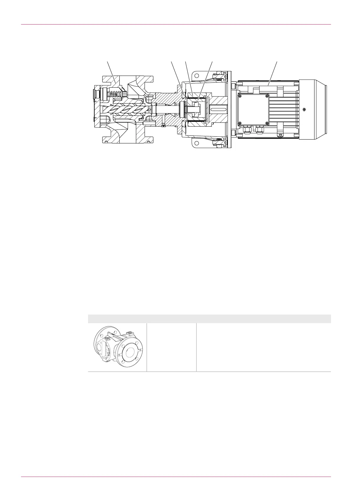
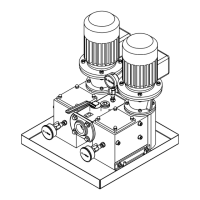
Fig.4: Pump unit structure
12 Pump 15 Inner rotor
13 Containment can 16 Motor
14 Outer rotor
5.3 Functional principle
Screw pumps are rotating pumps. Their displacement effect results from three rotating screws6 and11
and the enclosing pump housing3.
Radial support of the screw set is effected through the sliding contact in the pump housing that de-
pends on lubrication by the pumped liquid. Screw pumps are therefore not suitable for dry running and
can only be used up to specific pressure limits and viscosity limits. Due to the narrow tolerances pump-
ing of suspended solids is not possible.
Axial support of the main screw is effected by a deep-groove ball bearing. In order to reduce the pres-
sure, a balancing cylinder is mounted at the main screw. An integrated overflow valve protects against
excessive pressure that could cause housing parts to burst.
The default direction of the rotation of the screw set is clockwise viewed from the motor and is marked
on the pump flange by an arrow.
The flow direction is marked on the pump housing by two arrows.
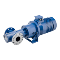
5.4 Housing variants
Housing Type Description
KF/KV Flange arrangement: Inline flange PN16
10
OIK 09en-GB Edition 2019-11
Operating instructions