12 Servicing
12.4 Replacing the magnetic coupling
5. Lift the motor off the pump bracket.
6. Depending on the motor size remove the threaded pin6 or the countersunk screw4.
7. Pull the outer rotor support5 and outer rotor7 off from the motor shaft using mounting levers.
8. Remove the socket screws8 between the outer rotor support and the outer rotor.
12.4.2 Removing the inner rotor
Personnel qualification: o Fitter
Personal protective equipment: o Work clothing
o Protective gloves
o Safety boots
Aids: o Hexagon key
o Anti-rotation screw
DANGER
Magnetic field.
Risk of death for persons with cardiac pacemaker, metallic implant or neurostimulator.
► Under no circumstances may persons with cardiac pacemakers, metallic implant or
neurostimulator perform work on the pump/pump unit.
Notice The containment can be dismantled more easily if it is heated to 80°C.
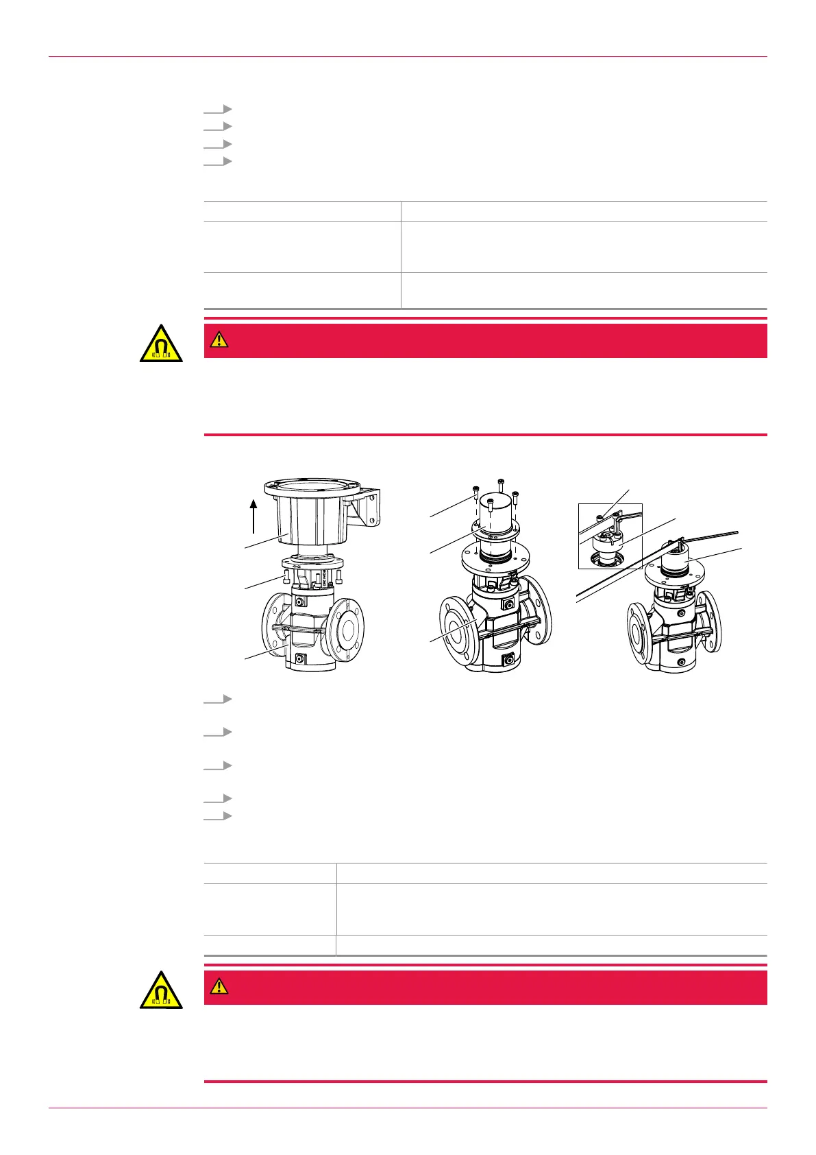
1. Remove the socket screws9 between the pump1 and pump bracket3 and remove the pump
bracket.
2. Remove the socket screws10 between the containment can11 and the pump and remove the
containment can.
3. To replace the inner rotor13, screw two screwsM into the empty threaded holes of the tension-
ing element12 as anti-rotation screws.
4. Remove the screws of the tensioning element.
5. Turn the screws back into the existing threaded holes.
ð This loosens the tensioning element from the inner rotor and from the pump shaft.
12.4.3 Installing the inner rotor
Personnel qualification: o Fitter
Personal protective
equipment:
o Work clothing
o Protective gloves
o Safety boots
Aids: o Oil without molybdenum sulphide additive (e.g. multifunction spray WD-40)
DANGER
Magnetic field.
Risk of death for persons with cardiac pacemaker, metallic implant or neurostimulator.
► Under no circumstances may persons with cardiac pacemakers, metallic implant or
neurostimulator perform work on the pump/pump unit.
32
OIK 09en-GB Edition 2019-11
Operating instructions