10 Operation
10.3 During operation
1. Open the pressure gauge shut-off valve.
2. Read the operating pressure and close the pressure gauge shut-off valve.
10.3.2 Monitoring filters and/or strainers
Notice The manufacturer recommends protecting the pump against soiling by means of a filter and/or strainer
installed at the system end (mesh width 0.5mm). The degree of soiling of the filter and/or the strainer
can be monitored by means of a suction-side pressure gauge or a differential pressure indicator.
Notice The manufacturer recommends protecting the pump against soiling by means of a filter and/or strainer
installed at the system end. The degree of soiling of the filter and/or the strainer can be monitored by
means of a suction-side pressure gauge or a differential pressure indicator. Mesh width Ä Technical
data,Page8.
Personnel qualification: o Trained personnel
DANGER
Magnetic field.
Risk of death for persons with cardiac pacemaker, metallic implant or neurostimulator.
► Under no circumstances may persons with cardiac pacemakers, metallic implant or neurostimu-
lator perform work on the pump station.
ATTENTION
Damage to equipment through unsuitable filter and/or strainer.
► Observe the mesh width Ä Technical data,Page8.
1. After commissioning monitor the degree of contamination of the filter and/or strainer by means of
a suction-side pressure gauge or a differential pressure indication.
2. Additionally check the filters and/or strainers at a pressure drop on the suction side. Observe the
dimensioning data of the manufacturer of the filters/strainers.
3. Check the suction-side pressure every two weeks during running operation.
10.3.3 Adjusting the overflow valve
Personnel qualification: o Fitter
Aids: o Hexagon key
Notice The opening pressure of the overflow valve is set to 110% of the differential pressure in the factory.
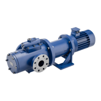
Fig.10: Overflow valve
1 Screw plug
2 Adjusting screw
3 Pressure spring
4 Valve body
Operating instructions
OIK 09en-GB Edition 2019-11
25