3. Connect the audio input signals to the AUDIO INPUT 3.5mm mini jack connectors
&
, as required (not shown in Figure 3).
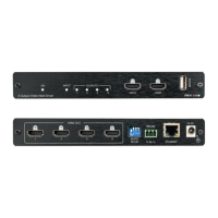
4. Connect the HDMI OUT connector to an HDMI acceptor (for example, an LCD
display).
5. Connect the HDBT OUT connector to an HDBT receiver.
6. Connect the AUDIO OUT 3.5mm mini jack connector to an unbalanced stereo audio
acceptor (not shown in Figure 3).
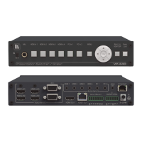
7. On the front panel, connect a microphone to the MIC 6.3mm phone jack and set it to
condenser or dynamic type.
8. Connect the power cord (not shown in Figure 3).
Connect the:
▪ RS-232 DATA 3-pin terminal block connector (Tx, Rx, G) to a PC for sending
RS-232 commands via HDBT.
▪ RS-232 CONTROL 3-pin terminal block connector (Tx, Rx, G) to a PC to
control the device.
9. Connect the INPUT SELECT 7-pin terminal block (contact-closure remote-control pins)
to select an input by momentarily pressing the switch.
10. Connect the ETHERNET port (see Operating via Ethernet on page 17).
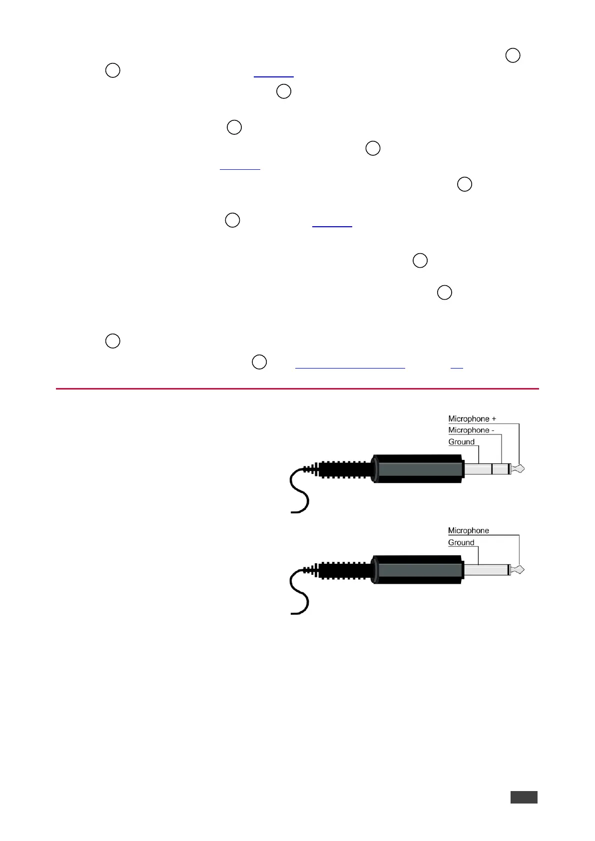
Microphone Pinout