Multitec
If there is not suitable torque wrench available for the
tightening of the shaft nuts, proceed as follows with respect to
each design :
Self-locking nut on drive end or non-drive end
(versions C and D)
• Tighten fast the shaft nut firmly
• Loosen the shaft nut again
• Apply adhesive to thread (e.g. LOCTITE)
• Moderately tighten the shaft nut
Nut with lockwasher on drive end
(or non-drive end versions C and D)
• Tighten the shaft nut firmly
• Loosen the shaft nut again
• Moderately tighten the shaft nut
• Bend over lockwasher
Nut with counter-nut on drive end or non-drive end
(versions C and D)
• Tighten fast first shaft nut firmly
• Loosen first shaft nut again
• Moderately tighten first shaft nut
• Block first shaft nut using suitable tool and tighten counter-
nut firmly against first shaft nut
Nut with counter-nut no non-drive end
(all versions except C and D)
• Moderately tighten first shaft nut
• Block first shaft nut using suitable tool and tighten counter-
nut closely against first shaft nut
Fixed bearings
The fixed bearing is the coupling-side bearing on the coupling
end. Deep groove ball bearings are installed in size 32. The other
sizes are equipped with angular contact ball bearings mounted
in X arrangement (see sectional drawing). The spacer discs 551.1
serve to position the rotor in axial direction.
Axial adjustment of the rotor in not required.
The correct axial position of the rotor is achieved by putting in
the bearing housing 350.1 spacer discs 551.1 to a total thickness
of 1.6 mm (1 x 1 mm + 3 x 0.2 mm) on the side of the bearing (or
angular contact ball bearings).
On previous versions, the axial alignment of the
rotor is set by putting on both sides of the bearing
(or the angular contact ball bearing) spacer discs 551.1 to a total
thickness of 1.6 mm.
The tightening of the cover bolts 901.1 (or 901.8 for oil-lubricated
bearings) must be done in diagonally opposite sequence taking
into consideration the tightening torques as follows :
MTC 32/50/65 30 Nm
MTC 100/125/150 40 Nm
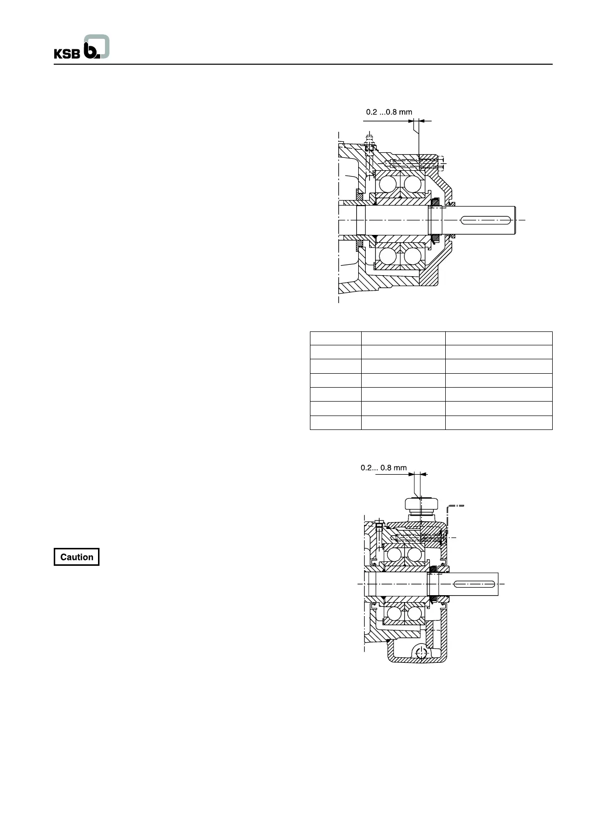
After installation of the bearings, the following controls need to
be made :
- Grease lubricated bearings : Check the clearance between
cover 360.1 and bearing housing 350.1 after having tightened
the bolts 901.1. There should be a clearance between 0.2
mm and 0.8 mm. The cover 360.1 must not rest on the bearing
housing 350.1.
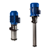
- Oil lubricated bearings : Check the clearance between cover
360.2 and bearing housing 350.1 by verifying the dimensions
prior to re-assembly (if bearings or cover have to be replaced).
Rolling element bearings
Grease lubricated bearings
Fig. 7.4-4
Pump size Drive end 320.1 Non-drive end 320.2
32 6309 ZZ C3-HT 6309 ZZ C3-HT
50 2 x 7309 BUA 6309 ZZ C3-HT
65 2 x 7309 BUA 6309 ZZ C3-HT
100 2 x 7312 BUA 6312 C3
125 2 x 7312 BUA 6312 C3
150 2 x 7315 BUA 6315 C3
Oil-lubricated bearings
Fig. 7.4-5
The same rolling element bearings will be installed for oil lubrication
as for grease lubrication.
Exception : Instead of bearing design 6309 ZZ C3-HAT, rolling
element bearing type 6309C will be used for oil lubrication.
21