✓ The motor has been set down in a horizontal position on a level and solid
surface. It has been secured against rolling off.
✓ Position the motor with the connections for the water storage tanks at the
highest point.
✓ The water storage tanks are on hand.
✓ The motor fill has been checked with the motor in vertical position.
✓ Suitable liquid for topping up the motor fill has been prepared.
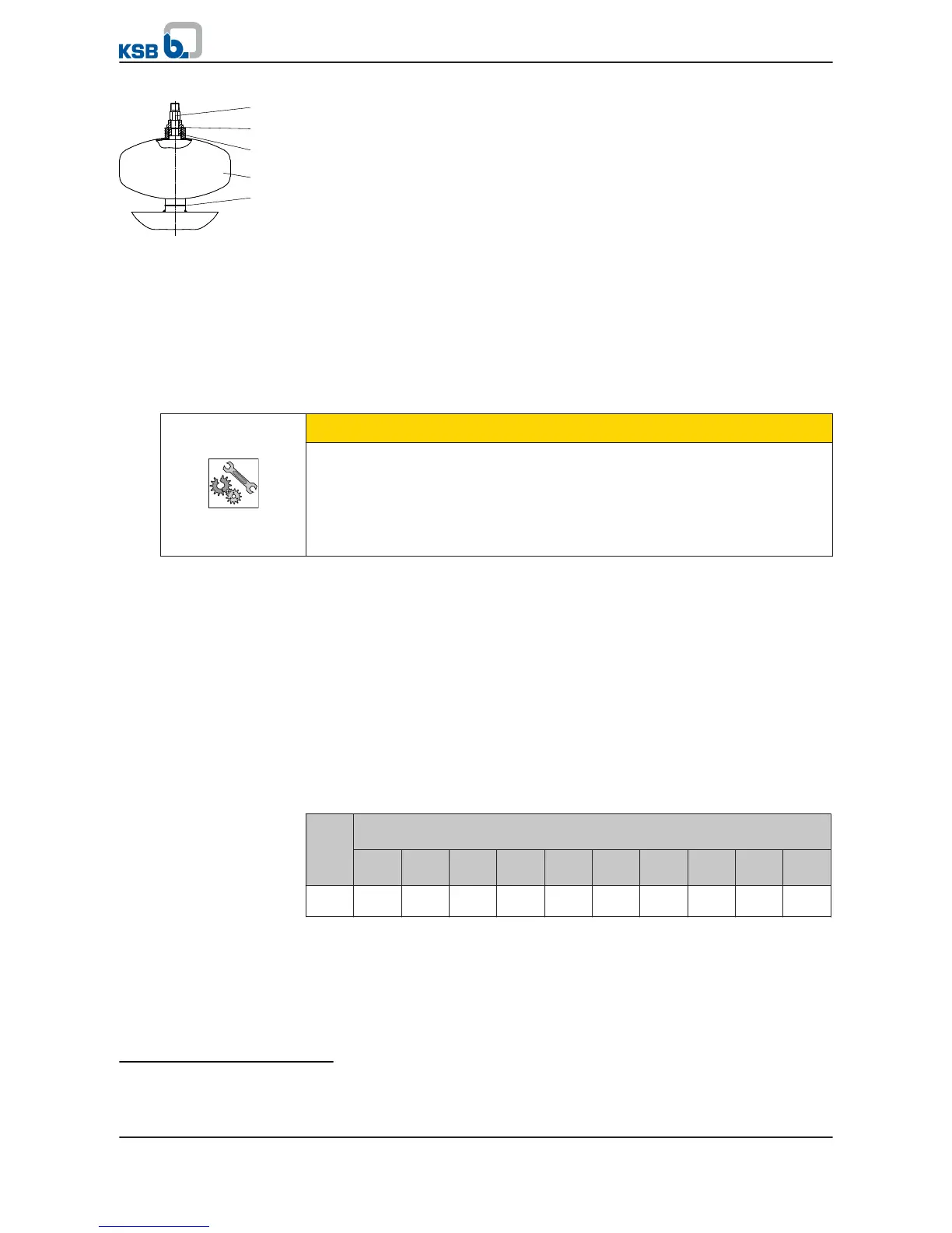
1.
Remove the screw plugs from the top and bottom of the stator case. Remove
the joint rings.
2. Insert the water storage tanks (59-33) with new joint rings (411.51) into the
stator and screw them in tightly.
3. Fill the water storage tanks with the specified liquid fill until they overflow.
4. Close both water storage tanks with a screw plug with integrated vent valve
(741) and joint ring (411.51).
5.2.5 Preventing backflow
CAUTION
Uncontrolled backflow of the fluid from the riser
Damage to the pump set!
▷ Prevent any uncontrolled backflow of the fluid handled with suitable means.
▷ Make sure that backflow of the fluid handled is slow and controlled, so that the
pump rotor does not start to rotate, e.g. by throttling the discharge-side gate
valve accordingly.
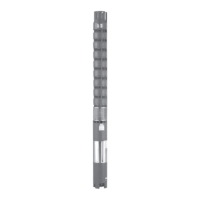
The submersible borehole pumps are generally fitted with an integrated non-return
valve.
On pump sets without non-return valve the operator must prevent any uncontrolled
backflow of the fluid, e.g. by structural means. Otherwise the pump could be
operated in the wrong direction of rotation and critical speeds could be exceeded.
5.2.6 Calculating the total weight
Suitable lifting equipment (e.g. tripod, crane, etc.) is required for installing and
removing submersible borehole pumps. The load-carrying capacity of the lifting
equipment must be larger than the weight of the pump set + the riser
7)
+ the water
column
8)
in the riser + the power cable + the cable ties. For the weights refer to the
order documentation, the product literature of the sub-suppliers and the following
table.
Table 8: Weight of the water column per 1 metre of the riser
Pipe diameter [mm]
Pipe diameter [inch]
50
2"
80
3"
100
4"
125
5"
150
6"
200
8"
250
10"
300
--
350
--
400
--
Weigh
t [kg]
2 5 8 12 18 32 49 72 98 125