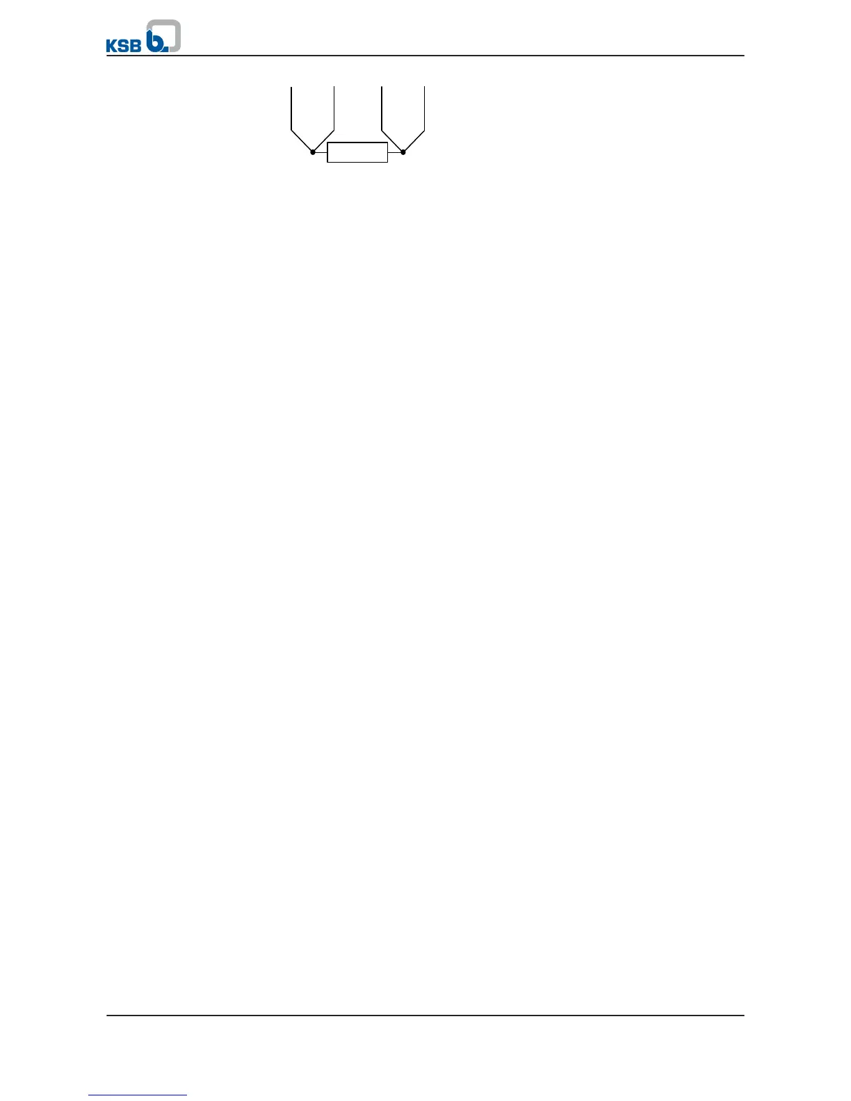
4-wire system
For 4-core cables only.
1. Core-to-core resistance (measure with d.c. voltage U < 6 V)
If the temperature sensor is intact, resistances between the individual cores shall
be as follows:
– Resistance between A1 and A2 / between A3 and A4: 0 Ω to 30 Ω
– Resistance between A1 and A3 / between A2 and A4: 100 Ω to 130 Ω
2. Insulation resistance (measure with d.c. voltage U < 100 V). Combine all core
ends.
– The resistance between the core ends and earth (e.g. motor housing) must be
higher than 6 MΩ.
Two temperature limits are important for submersible motors.
1. Alert temperature t
Alert
If the alert temperature t
Alert
is exceeded, a malfunction has occurred (e.g.
inadmissible contamination / ochre build up on the motor housing). Corrective
action must be initiated.
Setting:
t
Alert
= t
Operating
+ (t
Cut-out
- t
Operating
) / 2
t
Operating
= normal operating temperature after approximately 1.5 operating hours
2. Cut-out temperature t
Cut-out
If the cut-out temperature t
Cut-out
is reached, the motor must be tripped. It must
not be re-started until the malfunction has been remedied.
Setting:
Submersible motors with J2 winding (PE): t
Cut-out
= 75 °C
Testing:
Function
5 Installation at Site
38 of 64
UPA, UPZ, BSX