5. Insert #8 fiber washers into the mounting bracket’s
four mounting holes on both sides of the
mounting bracket (see Figure 2-11).
6. Insert #8 flat washers and #8 Phillips screws into
the mounting bracket’s four mounting holes from
above. Secure the bracket to the mounting surface.
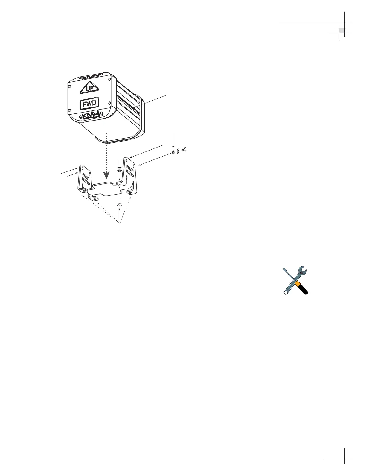
7. Place the sensor module in the bracket with the
proper orientation (up/forward).
8. Thread #10-32 screws through lock washers, flat
washers, and bracket, and then into the captive
extrusion T-nuts within the sensor module
housing, as shown in Figure 2-11.
Installation
54-0161
21
Figure 2-11
Securing the Sensor Module and
the Horizontal Sensor Bracket
Should you ever need to replace
the #10-32 screws used to secure
the housing to the bracket, the
screws must be no longer than
3
⁄8"
(10 mm) to avoid damaging the
housing.
 Loading...


