Option 2 - Mounting the Sensor to a Vertical Surface
1. Choose a mounting location based upon the
guidelines in “Choosing the Best Location for the
GyroTrac Sensor” on page 14.
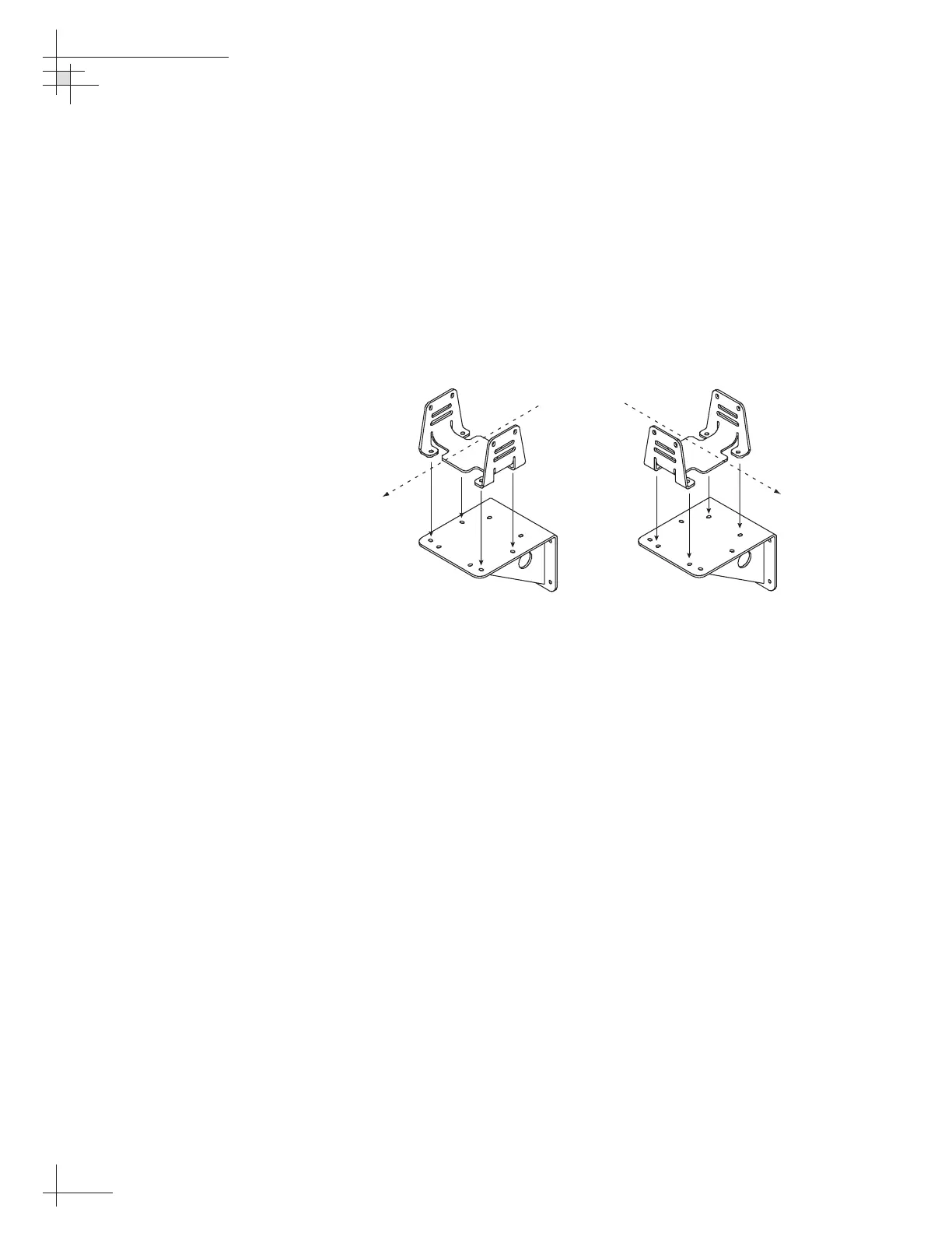
2. The module must be oriented so that the forward
reference on the end cap is pointed forward and
parallel to the vessel’s fore-and-aft axis (see
Figure 2-10 on page 20). The brackets are designed
so that the sensor module may be mounted
perpendicular or parallel to the mounting surface,
as pictured in Figure 2-12.
3. The module must be level with the vessel’s deck.
You may fine-tune this placement using the
ADCU’s pitch and roll data. Adjust the brackets so
that the pitch and roll are 0 (zero) when the vessel
is docked and under normal load.
4. When choosing a location for the unit, make
certain that there is sufficient overhead clearance
for both brackets and the sensor module.
5. Using the holes in the vertical sensor bracket as a
template, mark locations for the four mounting
screws. Center punch and drill the four holes with
a
1
⁄8" (3.5 mm) bit.
54-0161
22
TracVision G6 Technical Manual
 Loading...


