8. Clean the mounting surface where the foam seal
will be placed. Remove the paper backing from the
foam seal to expose the contact cement, then lay
the foam seal in place, adhesive side down, and
press down firmly to bring the adhesive into full
contact along the bottom.
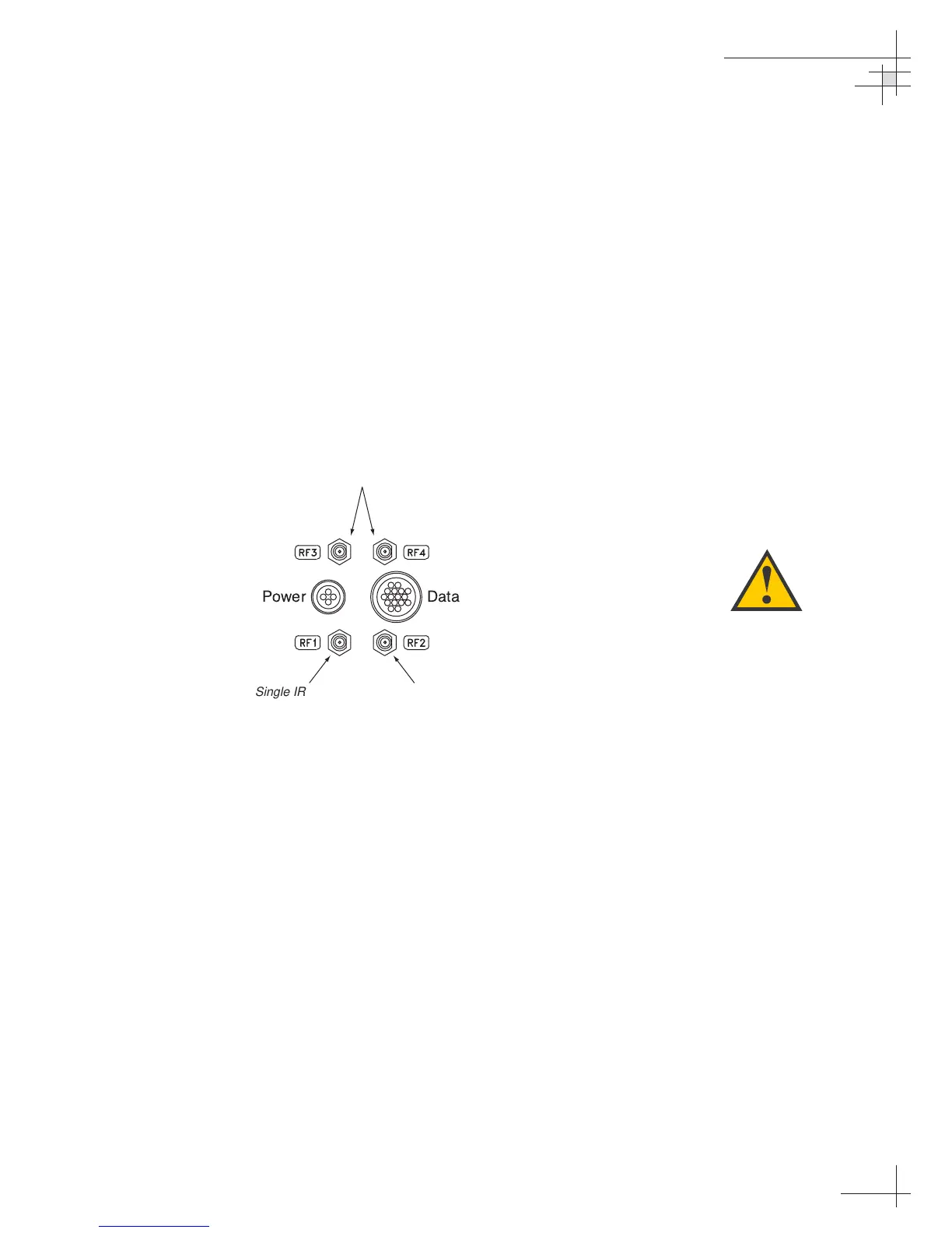
9. Bring the data cable, RF cable(s), and power cable
from below-decks up through the cable access hole
in the mounting surface. Connect the cables to the
baseplate as shown in Figure 2-6. Turn the
connectors down securely, but don’t use excessive
force; finger-tight is sufficient. If you are
connecting more than one RF cable, label both
ends of each RF cable to match its antenna
baseplate connector (RF1, RF2, RF3, RF4).
10. Place the antenna baseplate over the holes drilled
in the foundation, ensuring the “Forward” label
(shown in Figure 2-4) points toward the bow.
Installation
54-0161
17
Figure 2-6
Baseplate Connector Assignments
 Loading...


