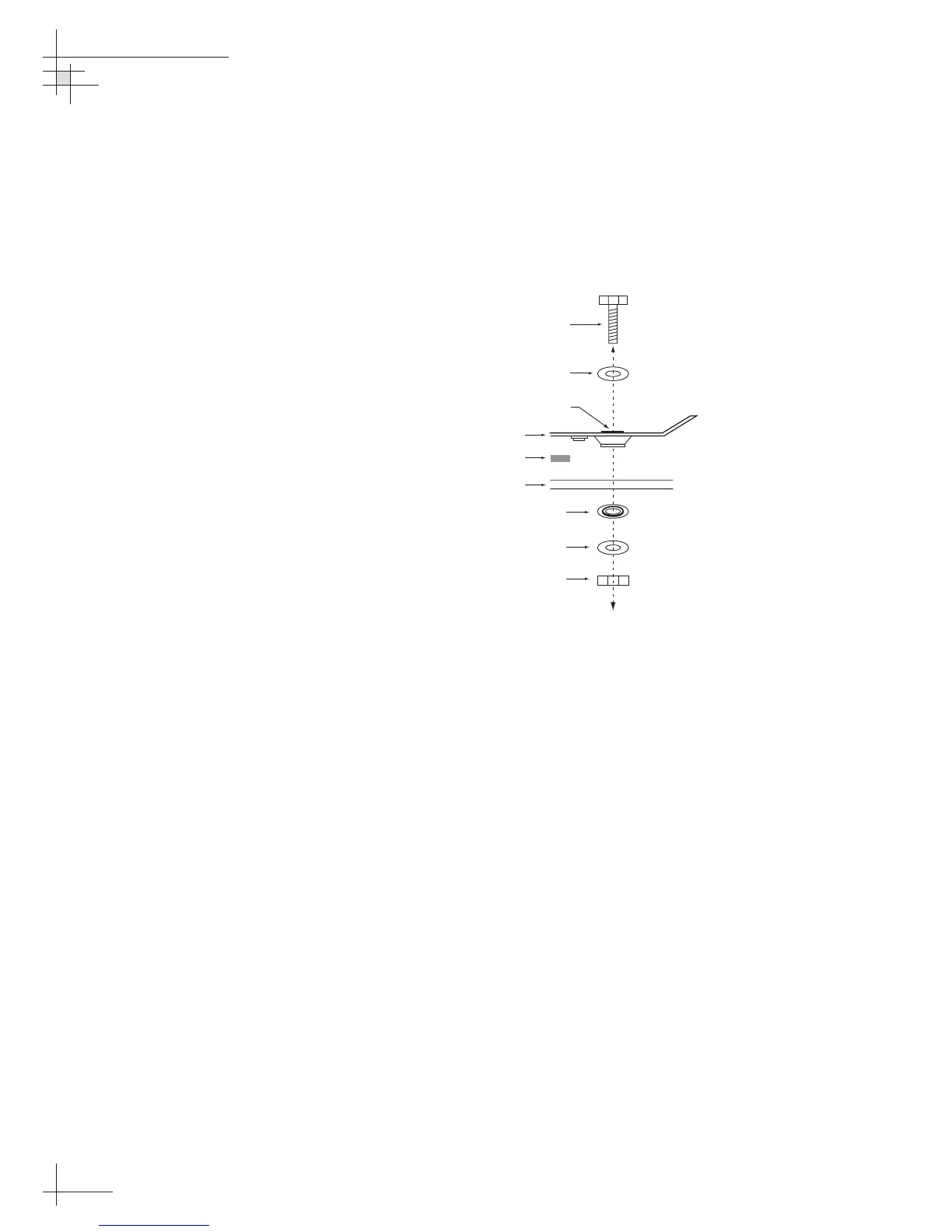
11. At each of the four baseplate mounting holes,
place a flat washer from the kitpack on a bolt and
insert the bolt into the hole from above, as shown
in Figure 2-7. Rotate the azimuth mechanism plate
to expose all four mounting holes. When rotating
the azimuth mechanism by hand, go slowly. Hitting the
stops with excessive force will damage the azimuth
limit switch.
12. Apply a fiber shoulder washer, flat washer, and
lock nut from below, as shown in Figure 2-7.
13. Tighten securely (but do not overtighten) until the
foam seal is compressed as far as it will go and all
four feet are bottomed against the mounting
surface.
14. If you are installing a European system, you will
need to adjust the skew angle on the antenna’s
LNB before installing the radome (see Section 2.8,
“Setting the Skew Angle” on page 55). If you are
installing a North American system, proceed to
Step 15.
15. Place the radome over the baseplate. Align the six
radome screw holes with the inserts in the
baseplate, insert the screws and tighten. Install a
protective plastic screw cap from the kitpack over
each screw.
54-0161
18
TracVision G6 Technical Manual
Figure 2-7
Bolting the Antenna Unit to
the Deck (Side View)
 Loading...


