FLAPS_V6_HBR_datasheet_manual_EN.odt
4.4 Electrical connections
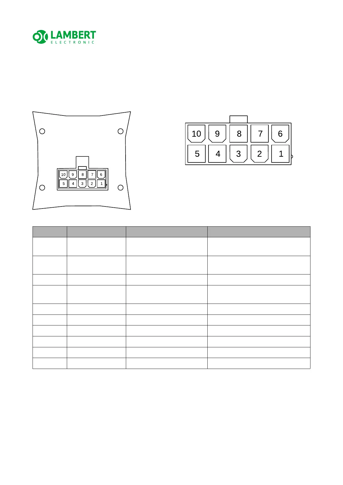
On the back of the device there is a 10-pin Molex Mini-Fit JR connector, which is used to
connect the actuator, position sensor, limit switches, LBUS pin, power supply.
The figure below shows a view of the back and connector with numbered pins:
Pin no. Signal name Description Notes
1 LIMSW_UP Limit switch – against flaps
rising
Opposite for inverse mechanical
coupling
2 LIMSW_DOWN Limit switch – against flaps
lowering
Opposite for inverse mechanical
coupling
3 POT_HI Position sensor supply (+)
4 POT_MID Position sensor feedback
signal
5 POT_LOW Position sensor supply (-)
6 V
IN
(+12V) Power supply (positive)
7 OUTB Motor power output B (+) for move flaps down
8 LBUS LBUS signal adjustable function
9 OUTA Motor power output A (+) for move flaps up
10 GND Power supply (negative)
ATTENTION! Use a suitably rated fuse in the power supply.
NOTE It is recommended to use shielded cabling, especially for motor conductors (to
reduce radiated noise from the motor). Connect the shield to GND ONLY on the control
unit side. NEVER at both ends!
17/33
view of the connector in the control unit