FLAPS_V6_HBR_datasheet_manual_EN.odt
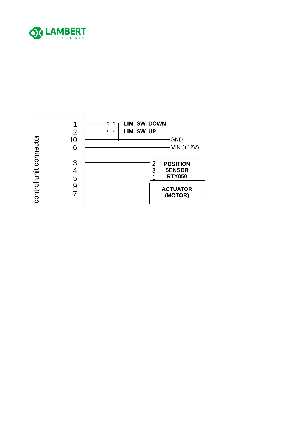
4.4.2 Electrical connections with simple actuator, external position
sensor and limit switches
If your actuator does NOT include a position sensor or limit switches, it is NECESSARY TO
CONNECT EXTERNAL ONES. Connect the control unit according to the following diagram,
with an example of external limit switches and Honeywell RTY050 position sensor.
ATTENTION! Always check with care that the actuator moves the flaps in the intended
direction and not vice versa. If it moves the other way around, the motor wires are
probably swapped. This test should be performed WITHOUT a connected position sensor,
when the control unit enters Safety (manual) mode and therefore this test will not be
affected by a potentially inverted position sensor (which is second option what coud be
wrong).
ATTENTION! Always make sure that it stops the actuator for the direction to be
protected before final mounting each of the limit switches. If it stops in the opposite
direction, then reverse the electrical connection of the switches – i.e. swap pins 1 and 2
on the control unit connector.
ATTENTION! When using a digital electronic position sensor (such as the RTY050), make
sure the polarity of the power supply is correct. Always read the sensor manual (different
EU and US pinning). Follow the table in chap. 4.4 of this manual describing the pins on the
control unit connector.
19/33