FLAPS_V6_HBR_datasheet_manual_EN.odt
4.4.1 Electrical connections of actuator with internal position
sensor and limit switches
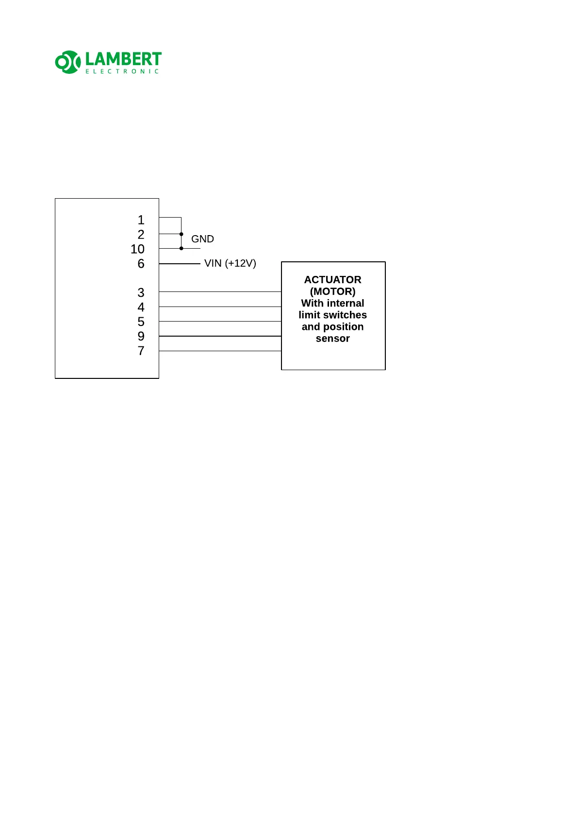
If the actuator you are using contains both a position sensor and limit switches, connect
the control unit according to the following diagram.
ATTENTION! Always refer to the documentation for the actuator used to identify the
appropriate signals for the motor and position sensor. Then connect to the corresponding
pins of the control unit connector, which are described in the table in chapter 4.4.
ATTENTION! If pins 1 & 2 are not connected to GND via external wiring, the
control unit will NOT work properly !
ATTENTION! Always check with care that the actuator moves the flaps in the intended
direction and not vice versa. If it moves the other way around, the motor wires are
probably swapped. Then this test should be performed WITHOUT a connected position
sensor, when the control unit enters Safety (manual) mode and therefore this test will not
be affected by a potentially inverted position sensor (which is second option what coud be
wrong).
18/33