FLAPS_V6_HBR_datasheet_manual_EN.odt
5 Description of functions
5.1 Normal mode – automatic
• as soon as the power is switched on, the control unit performs the initialization
sequence, which is indicated by the successive lighting of all LEDs first in red, then
gradually by changing the color of each LED from red to green; at the end of the
initialization sequence all LEDs turn off
◦ this initialization sequence allows to verify that all LEDs of the device are
working, each red and green color (orange is created by mixing both)
• after the initialization sequence the device waits for a command regardless of
whether the flaps are in the position corresponding to the switch or not
◦ the actual real position of the flaps is indicated by the corresponding position
LED (for more information see the position indication table later in this chapter)
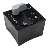
• by turning the rotary switch to one of the positions 0,1,2, (3) (corresponding to the
positions of the flaps 0°, 10°, 20°, 30°; possibly another scaling according to the
user settings and the used variant HBR or HBR 3P, which has only position 0-2) the
unit starts the automatic adjustment of the flaps by means of the electric actuator
to the desired position
• the progress of the adjustment is indicated by the orange LEDs of the individual
flaps positions, which are currently passed through until the stop at the given
position indicated by the green color of the LED corresponding to the given position
Flap position indication table:
Indication Meaning Notes
lights
the flaps are in the range of the position
of the respective LED (stopped or in
motion)
lights
the flaps are located exactly at the
position selected by the switch and are
stationary
flashes 1x/s
(slowly)
the flaps are located behind the position
of the respective LED (out of the range of
positions set by positions 0,1,2,(3)) and
stand still
indicated at end positions 0 and
3 (2 for HBR 3P)
21/33
 Loading...