FLAPS_V6_HBR_datasheet_manual_EN.odt
2.4 Controls
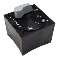
The flaps control unit has the following controls:
• rotary switch with 3 to 4 positions (depending on type)
• 2 SET buttons
2.5 Outputs
The flaps control unit has the following outputs:
• motor power output
• output to landing gear control unit (shared with dimmer signal input function)
2.6 Indication
The flaps control unit has the following indication elements:
• 4x two-color LED (positions correspond to the rotary switch, by combining it is
possible to achieve a total of 3 colors - orange, red, green)
The indication in this manual is represented by pictograms with the following
meaning:
LED emits some color (orange, red, green)
LED is off
LED slowly (1x/s) flashes in some color (orange, red, green)
LED fast (5x/s) flashes in some color (orange, red, green)
LED slowly (1x/s) alternates two colors
LED quickly (5x/s) alternates two colors
2.7 Protections
The flaps control unit has the following protections:
• reverse polarity protection
• protection against overvoltage spikes of both polarities
• protection against interference and short circuit at the potentiometer input
• Undervoltage protection
• High temperature protection
• short circuit protection at motor output
7/33