FLAPS_V6_HBR_datasheet_manual_EN.odt
5.6 Landing gear control output
If the LBUS pin function is set as the landing gear control output (factory default), then
the output behavior is as follows, depending on the rotary switch setting:
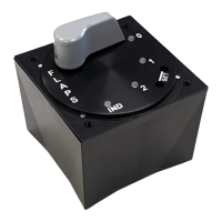
• Turning the rotary switch to position 2 or 3 activates the LBUS output
• Turning the rotary switch to 0 or 1 disables the LBUS output
ATTENTION! The landing gear control output is intended solely for connection
to the corresponding input of landing gear control unit manufactured by
LAMBERT ELECTRONIC s.r.o.
5.7 Dimming of indicator elements
Dimming of indicator elements is possible only if the following conditions are met:
• DIMBOX accessory is connected to the FLAPS V6 HBR control unit
• the control unit has been configured to dim by the LBUS pin
• the DIMBOX accessory input is connected to a dimmer output that is at a common
potential as DIMBOX and FLAPS and outputs positive PWM pulses of the
appropriate voltage level and frequency
When the dimmer is turned off, set to minimum or disconnected, the unit maintains
internally set minimum functional intensity of the indicator elements – i.e. the indicator
elements never turn off completely.
ATTENTION! NEVER connect a dimmer directly to the FLAPS control unit!
Always via DIMBOX accessory. Direct connection may result in damage to the
FLAPS unit.
28/33