FLAPS_V6_HBR_datasheet_manual_EN.odt
4.4.3 Electrical connections for dimming control unit display
elements
ATTENTION! Never connect the dimmer directly to the control unit (without
DIMBOX accessory) !!! The control unit may be irreversibly damaged!
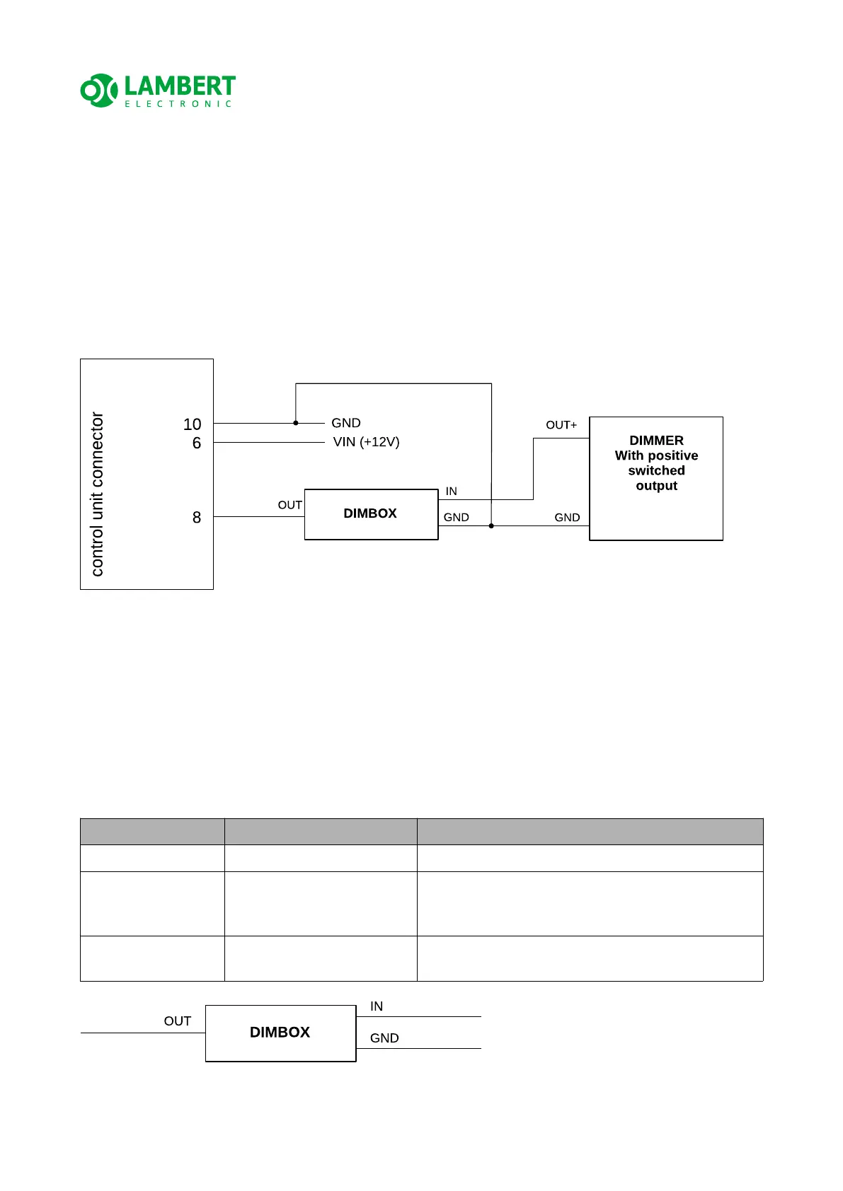
The figure below shows the wiring diagram for dimming of the indicator elements. It
shows how to connect the dimmer via DIMBOX (accessory to the FLAPS V6 HBR control
unit).
ATTENTION! For simplicity, the diagram does not include other important elements and
connections mentioned in the previous chapters! Only those that are necessary to explain
the wiring for dimming the indicator elements.
ATTENTION! To use the indicator dimming function, you must configure the control unit
as described in chapter 5.5 Device Setup Mode.
DIMBOX accessory has fixed wires marked with labels, more info in the table below:
Wire label Signal function desc. Notes
OUT DIMBOX output to LBUS input of control unit FLAPS V6
IN Positive input for dimmer
signal - PWM 10 ÷ 16 V,
80 ÷ 200 Hz
Dimmer with positive output PWM switching
connected to the same potential as the control
unit and DIMBOX
GND Negative power supply (-) Connected to the same GND potential as the
control unit
20/33