HVM200 Reference Manual Electrical Characteristics A-6
• External Power:
USB Type A to Micro-B USB cable, 3 ft (1 m)
Larson Davis Power Supply PSA035 (universal 100-240 VAC to 5 V USB power adapter)
A.4.3 Electrical Testing
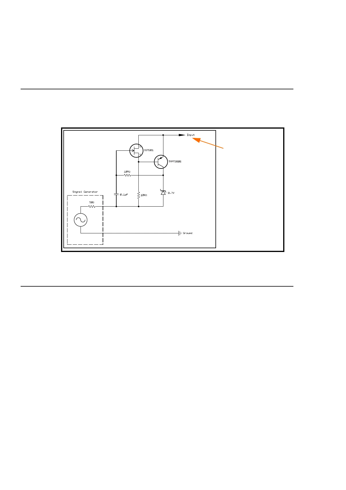
During electrical testing, the following circuit was used:
Circuit to Inject Electrical Signal into HVM200 ICP
®
Inputs
A.4.4 Input
• Input type: ICP, IEPE, or CCP
• Excitation current: 2 mA
• Input connector: 1/4-28 4-pin male (the input connection is also the transducer connection)
• Measurement input voltage range: 1.8 to 16 Vdc
• Measurement AC reference bias voltage: 9 Vdc
• Absolute voltage range (min to max): 0 to 28 V
• Bandwidth: 0.4 Hz to 3000 Hz
• Range: Single range
• Sample rate: 7161.45833 Hz
Represents one
input for each axis
(x,y, z).
Refer to the “Pin-
out” diagram
below for more
information on the
1/4-28 input con-
nection.