HVM200 Reference Manual Connecting the Accelerometer 2-9
Step 3 Connect via TCP/IP. Click the Add Meter button.
Step 4 Place your cursor in fields and enter the IP address.
Step 5 Once IP address is entered, the Connect button will turn
blue, select it.
TAKE NOTE IP address is the only
required field to add a meter, unless a
password has been created.
Step 6 Click the Live View button. The Live View presents the
same interface as the HVM200 App for working with mea-
surements.
2.7 Connecting the Accelerometer
LEARN MORE Refer to the "Hand-
held Shaker for vibrational measure-
ment verification" in this manual for
information on selecting the proper
accelerometer for the HVM200
meter.
To connect the accelerometer to your HVM200 meter, follow these steps:
Step 1 Insert the accelerometer cable into the 4-pin connector on
the HVM200 and then rotate the nut on the cable until the
connection is tight.
Step 2 Insert the other end of the accelerometer cable into the 4-pin
connector on the accelerometer and tighten the cable nut.
Step 3 If the HVM200 is not already turned on, press the power
button once, the Power LED will turn blue.
Step 4 Connect the HVM200 to G4 via USB.
LEARN MORE For more informa-
tion on working with G4 tabs and set-
tings, refer to the G4 LD Utility
Software Manual.
Step 5 Click the Setup Manager tab in G4. Under the meter set-
tings (displaying the meter serial number) click the Sensor
tab.
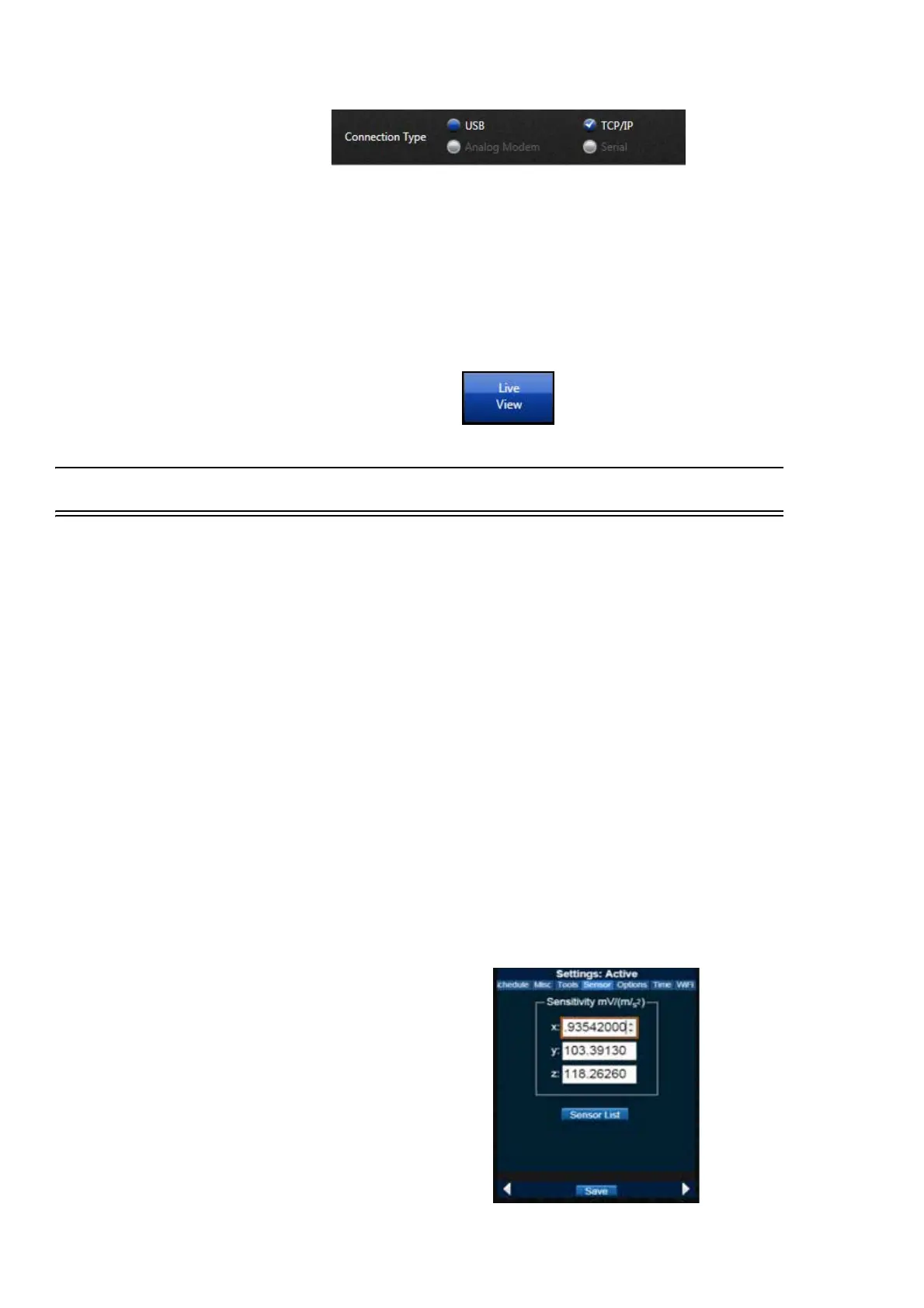
TAKE NOTE If you are using an
accelerometer with Transducer Elec-
tronic Data Sheet (TEDS) capabili-
ties, the sensitivity values will
already be displayed for the x, y, and
z axes of the sensor.
FIGURE 2-15 Sensor Settings