PLMNL0243 REV. A, Effective Date: 03/24/16 7 FiberMINI ™ 2.0 Operation Manual
3 Electrical Installation
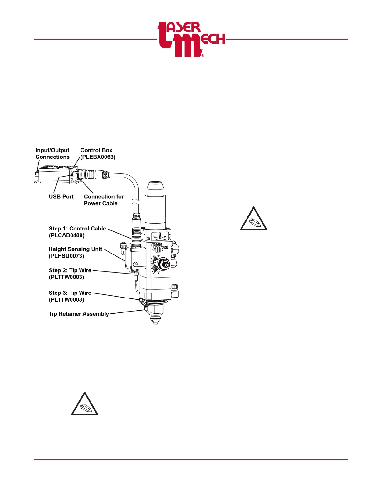
3.1 Electrical Connections
There are two connections to the height
sensing unit (PLHSU0073) and one to the
tip retainer assembly (PLTRA0449 or
PLTRA0432). See Figure 9. PLTRA0449
is shown as an example.
Figure 9
1. Insert the female end of the control
cable into the top of the height
sensing unit.
2. Insert the straight end of the tip wire
into the bottom of the height sensing
unit.
It may be helpful to wrap
the tip wire around the tip
retainer assembly during
installation.
3. Insert the right angle end of the tip
wire into the tip retainer assembly.
There are (4) connection locations for the
control box.
For steps 4 to 6, see Figure 10.
4. Insert the male end of control cable
into the 14-pin connection on the
electrical control box (no label). See
Figure 9.
5. Connect the user-supplied, 24V DC
power source to the three position
terminal block on the control box
labeled POWER.
The USB port provides the
interface connection
between the HSU and a
computer. Laser
Mechanisms provides PC
software called Basic+
HSU Utility that allows
monitoring of the HSU and
changing the HSU settings.
6. Connections to your system are made
through the 12 position terminal block
on the control box.
There are 3 optically isolated
outputs (Ready, Touch, and
Status), one optically isolated input
(Cal), one analog input (V
ref
), and 2
analog outputs (V
dif
, V
hsu
).