PLMNL0243 REV. A, Effective Date: 03/24/16 1 FiberMINI ™ 2.0 Operation Manual
1 Introduction
FiberMINI
®
2.0 is available in both straight line
and right angle configurations. Both styles are
simple, yet flexible to optimize the processing
head and the end user’s fiber laser. The head
is capable of cutting a wide range of materials
and available in various welding configurations.
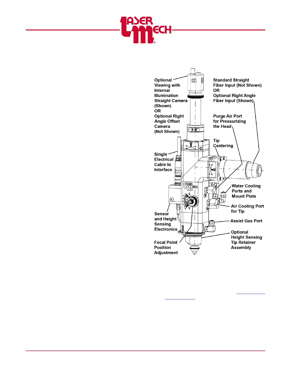
See Figure 1. FiberMINI
®
2.0 can be
configured with:
Straight or Right Angle Fiber Input
Straight, Right Angle, or Offset camera
vision
Internal illumination for all camera options
Coaxial Nozzle connections
Key Features
Flexible design to optimize spot size
Available with and without capacitive height
sensing
13 mm of lens movement to set focus
Quick and easy access to the cover slide
Water and Air Cooling
Smooth assist gas flow
Internal wiring and plumbing for gasses and
coolants
Compact, lightweight design
Compatible with all leading fiber-delivered
laser systems up to 4kW and all weld-
monitoring systems.
Fully Sealed Optical Path
Extra Cooling for Higher Power Rating
Figure 1
This manual explains the steps of installation,
setup, operation and service of the FiberMINI
2.0
®
product line. FiberMINI
®
2.0 is available in
many diverse configurations. See Appendix D –
Configurations and the supplied assembly
drawing to identify the components in your
custom FiberMINI 2.0
®
.