PLMNL0243 REV. A, Effective Date: 03/24/16 34 FiberMINI ™ 2.0 Operation Manual
5.8.1 Servicing the Camera Mount
Before opening any part of the head,
clean off the dust and/or process
debris using an exterior cleaning
towel (PLTLS0023) or equivalent.
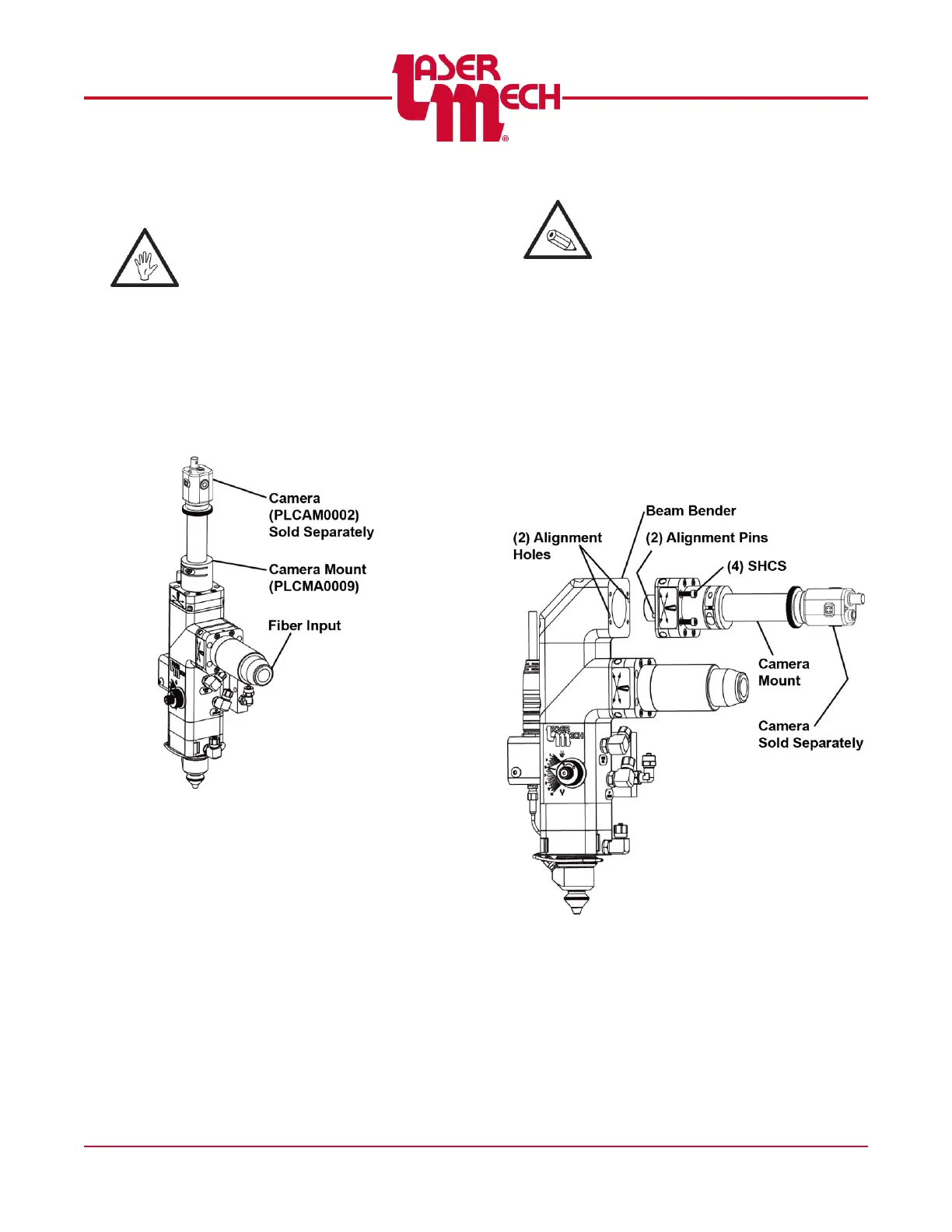
The camera mount is oriented using
(2) 4mm diameter dowel pins and
secured to the splitter cap using (4)
M4 SCHS.
See Figure 47 for the straight style
camera mount.
Figure 47
The M4 SHCS and the 4 mm dowel
pins are located in the camera mount
assembly.
Verify that the (2) alignment pins
are in-line with the
corresponding alignment holes.
To remove the camera mount
loosen the (4) M4 SHCS.
To install the camera mount
tighten the (4) M4 SHCS.
See Figure 48 for the right angle
style camera mount.
Figure 48