PLMNL0243 REV. A, Effective Date: 03/24/16 2 FiberMINI ™ 2.0 Operation Manual
2 Mechanical Installation
See Appendix E – Service Dimensions for
helpful assembly dimensions and notes.
2.1 Mounting
FiberMINI
®
2.0 processing heads have
integrated mounting holes in the adapter
plate. Two mounting styles are available.
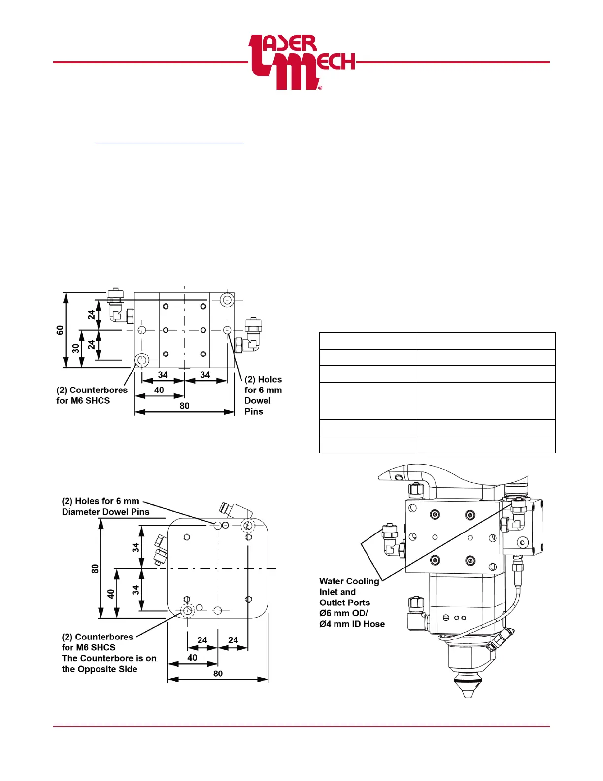
Without Crash Protection
Figure 2 illustrates the hole pattern in
PLADP0271 used for mounting the head.
Figure 2
With Crash Protection
Figure 3 illustrates the hole pattern in
PLCPD0089 used for mounting the head.
Figure 3
2.2 Plumbing
Water Cooling
FiberMINI™ 2.0 processing heads are
equipped with a water-cooling circuit.
It is recommended that power levels
greater than 1kW use water cooling.
Power level should never exceed
4kW.
See Figure 4 for location and hose
size. See the table below for
recommended specifications.
The cooling circuit is designed to be
operated on either a closed-looped
cooling system or facility tap water – as
long as the requirements in the table
below are met.