PLMNL0243 REV. A, Effective Date: 03/24/16 8 FiberMINI ™ 2.0 Operation Manual
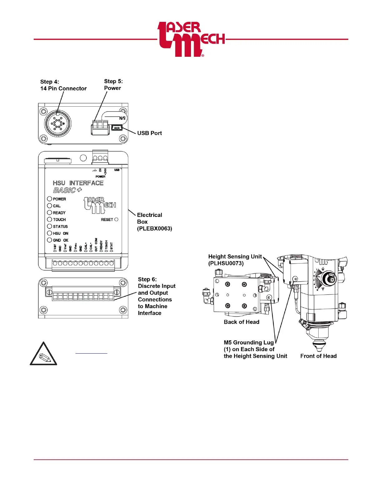
Figure 10
See Appendix B for an interface example.
3.2 Electrical Grounding and Noise
The capacitive sensing circuitry contained
in the FiberMINI™ 2.0 cutting head
measures minute changes in electrical
capacitance between the tip and earth-
ground to determine tip-to-part standoff
distance. In order for this circuit to function
properly the part and the cutting head
need to be connected to a good earth
ground.
Ideally the ground should be
established from a ground rod,
approximately 2 meters in length
driven into the ground located near
the base of the machine.
A large gauge (1.6mm diameter or
larger) ground wire should be run from
the ground rod to the part.
Run a separate wire from the ground
rod to the mount of the FiberMINI™
2.0. See Figure 11.
Figure 11
Electrical noise can create sensing issues.
Large electric motors, arc welders and
other devices may be a source of
significant electrical noise. In order to
eliminate this noise it may be necessary to
connect a ground wire to the chassis of
any such device near the process.