PLMNL0286 REV. B, Effective Date: 06/06/19 37 FiberMINI
®
with Auto Focus (AF) Operation Manual
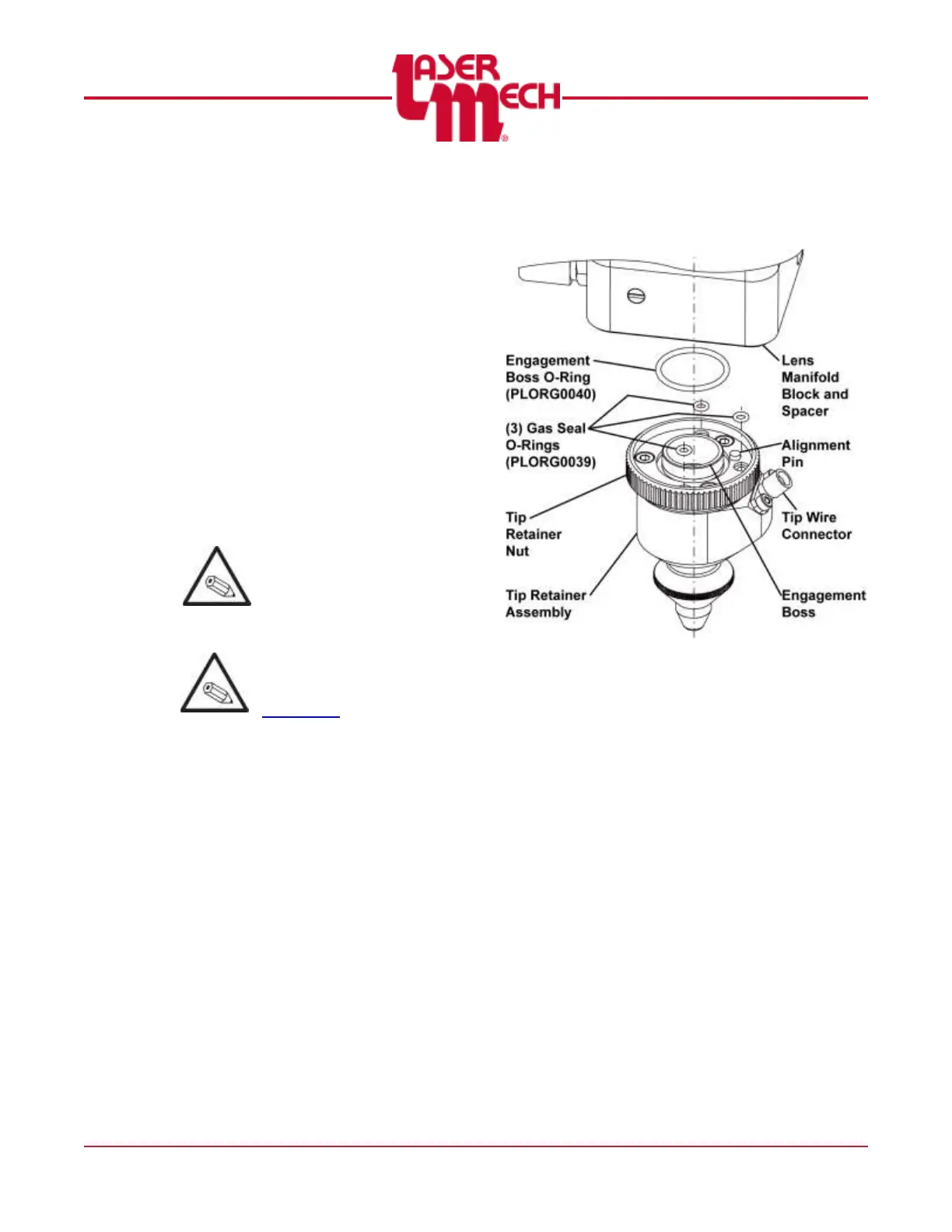
For steps 3 to 8, see Figure 47.
To remove the tip retainer assembly:
3. Note the orientation of the tip wire
connector for reinstallation of the tip
retainer assembly.
4. Using the retainer nut, unthread the
tip retainer assembly from the lens
manifold block spacer.
To install the tip retainer assembly:
5. Verify that the engagement boss
o-ring (PLORG0040) and (3) gas seal
o-rings (PLORG0039) are in place in
the top of the tip retainer assembly.
Replace any o-rings, if they are
damaged or missing.
Take care that the
engagement boss is in
line with the center of the
beam path.
If it is necessary, now is a
convenient time to replace
the tip according to
Section 5.2.
6. Center the tip retainer assembly on
the lens manifold block spacer.
7. Rotate the tip retainer assembly so:
The tip wire connector is in the
same orientation as noted in step
3.
The alignment pin seats into the
appropriate hole in the lens
manifold block.
8. Thread the tip retainer nut onto the
lens manifold block spacer.
Figure 47
9. Thread the tip transformer wire onto
the tip retainer assembly. See Figure
46.