PLMNL0286 REV. B, Effective Date: 06/06/19 41 FiberMINI
®
with Auto Focus (AF) Operation Manual
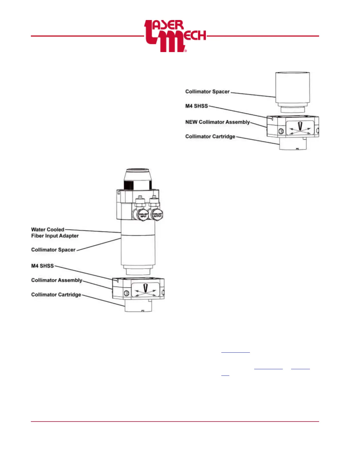
For steps 9 and 10, see Figure 52.
9. Loosen, but do not remove, the M4
SHSS securing the collimator spacer
to the collimator assembly.
10. Unthread the collimator spacer and
water cooled fiber input adapter out of
the collimator assembly.
The removed components are
glued together.
Keep both components as an
assembly; they are used later in
the process.
Figure 52
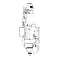
For steps 11 to 13, see Figure 53.
11. Locate the NEW collimator assembly.
12. Loosen, but do not remove, the M4
SHSS securing the collimator spacer
to the new collimator assembly.
13. Unthread the collimator spacer out of
the collimator assembly.
The new collimator assembly
ships with a collimator spacer that
must be removed.
Figure 53
For steps 14 to 18, see Figure 51.
14. Thread the EXISTING collimator
spacer and water cooled fiber input
adapter (removed in step 10) into the
NEW collimator assembly.
15. Tighten the M4 SHSS securing the
EXISTING collimator spacer to the
NEW collimator assembly.
To install the collimator assembly:
16. Position the head so the fiber input is
HORIZONTAL. See Figure 50.
17. Align the NEW collimator assembly
so:
The (2) ᴓ4 mm alignment pins are
in line with the ᴓ 4 mm alignment
pin holes in the head.
The (4) counterbored holes for M4
SHCS are in line with the M4
tapped holes in the head.
18. Insert and tighten the (4) M4 SHCS.
19. Install the fiber optic cable into the
cutting head according to the fiber
manufacturer’s instructions and
Section 2.4.
20. Center the beam in the tip orifice
according to Section 2.5 or Section
2.6.