3.
Sensor
3.1 Connection
The sensor simulation function can accurately judge the quality of the sensor
and reduce blind replacement of accessories. For example, the DTC shows that
the water temperature sensor is faulty, but whether it is the fault of the water
temperature sensor itself, or the wiring between the sensor and ECU, or the fault
of the ECU itself still needs further diagnosis. At this time, the signal of the water
temperature sensor can be simulated by the simulation function instead of the
water temperature sensor and inputted to the microcomputer. If the engine
working condition is improved and the fault symptom disappears, it can be
judged as a fault of the water temperature sensor. If the fault symptom persists,
directly input the signal at the corresponding terminal of the ECU. If the fault
symptom disappears, it is the wiring fault between the water temperature sensor
and ECU. If the fault symptom persists, it can be judged as a fault of the ECU
itself.
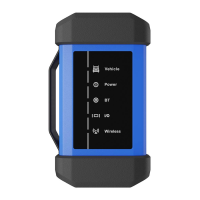
The following connections are required for detecting sensors:
1)
Connect the sensor module to the diagnostic tool via the USB cable (refer to
Chapter 2.1).
2)
Remove the sensor connected to the ECU.
3)
According to the specific application and bus terminal types, make the
following connections (note: when performing the sensor functions, the
hardware output ports of the sensor module are CH1 and CH2).
www.diagtools.eu, Pernavas 43A, Riga, Latvia, LV-1009, +37129416069, info@diagtools.eu