Drag the CH1 PEAK slider to change the output amplitude.
Drag the CH1 FREQ slider to change the output frequency.
X is used to change the output quantity of square wave x. Y is used to change
the output quantity of the straight line y.
*Remarks: X indicates how many square waves are output at a time. Y indicates how
many linear voltages are output after the output of X (the period of X square wave is 1).
The values of X and Y are determined by the actual hardware parameters.
5)
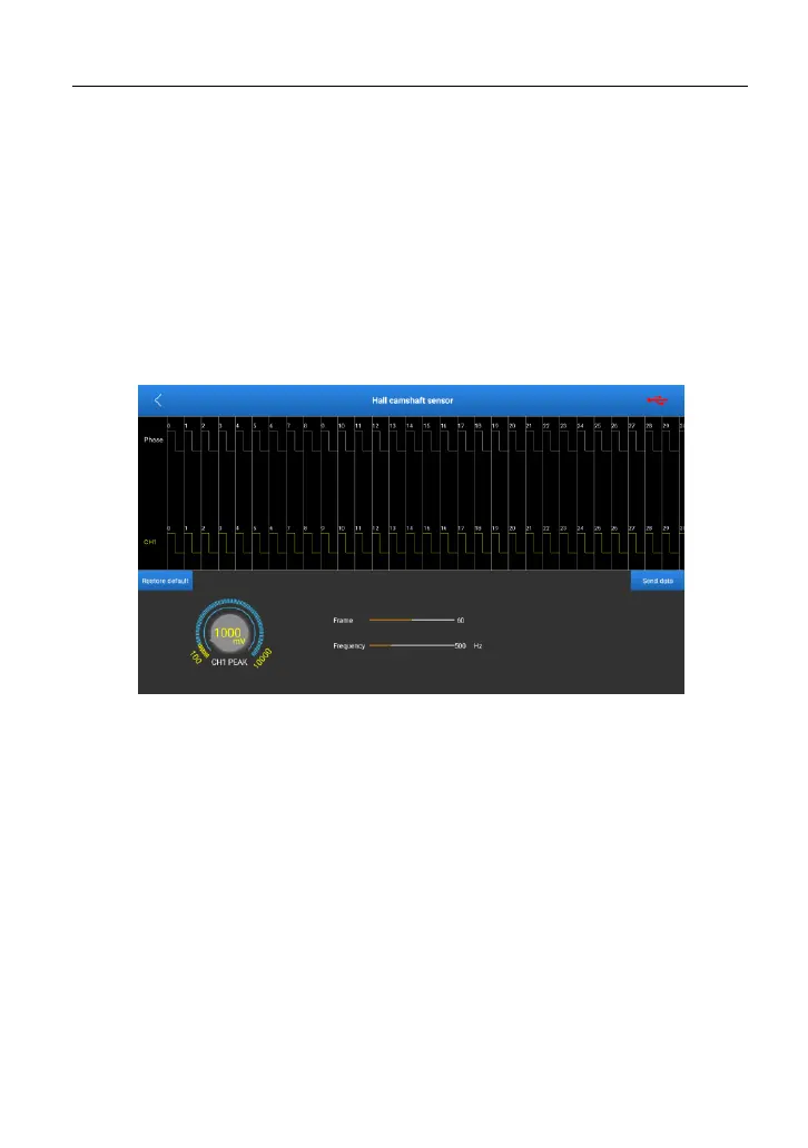
Hall camshaft sensor
Output channel: CH1
Output type: square wave
Drag the frame slider to change the total number of frames that is output at a
time.
Drag the frequency slider to change the output frequency.
Turn the knob of CH1 PEAK to change the amplitude value.
*Remarks: Phase is the clock. The frame number indicates how many
clock-corresponding waveforms are output at a time (for example, for 50 frames, 50
waveforms will be output cyclically). The waveform corresponding to the upper CH1 is
compatible (there are positive square wave, reverse square wave, linear voltage). Users
can edit them as required (the specific parameters are determined by hardware
parameters). For details, see Timing waveform.
www.diagtools.eu, Pernavas 43A, Riga, Latvia, LV-1009, +37129416069, info@diagtools.eu