Lenord+Bauer 4 DescriptionComponents and function
GEL 2444 55
English
4.2 Components and function
5
4
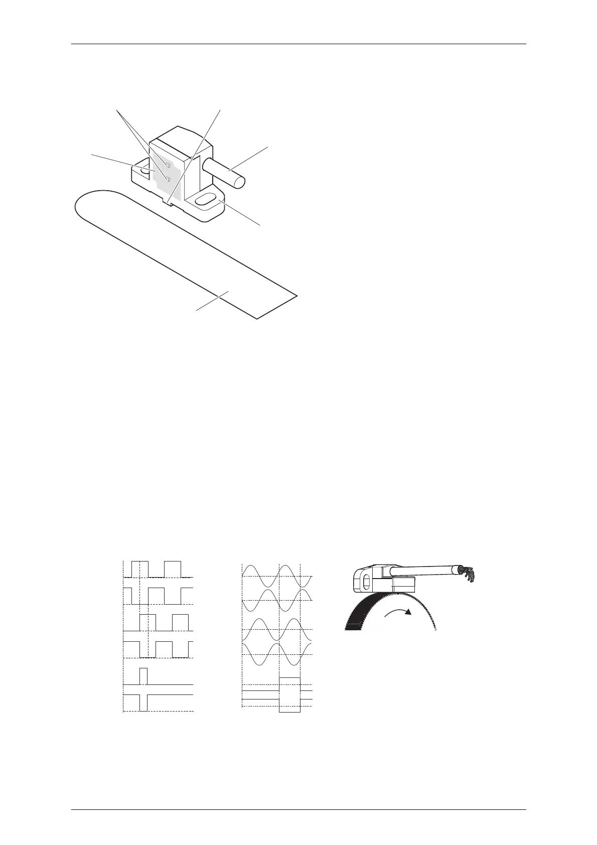
Example illustration for GEL 2444
1 Measuring surface
2 Sensor elements
(bottom: signal track,
top: reference track)
3 Guide lug
4 Connection cable
5 Mounting flange
6 Distance gauge
(e.g. 0.2 mm)
The MiniCODER is fastened to the mounting via the mounting flange (5) using two
screws. The exact positioning of the MiniCODER is ensured with the aid of the two
guide lugs (3) on the rear of the MiniCODER. For straightforward mounting, a non-
ferromagnetic distance gauge (6) of suitable thickness is included in the scope of
supply (thickness is dependent on the module).
The sensitive sensor elements (2) are under the measuring surface (1).
The integrated electronics are supplied with power via the connection cable (4).
The MiniCODER has a magnetic field that is changed by the rotating target wheel.
The sensor acquires the change in the magnetic field and the integrated electronics
convert this information into appropriate output signals.
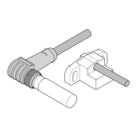
U
2+
U
2-
U
1+
U
1-
U
N+
U
N-
GEL 2444D
GEL 2444T
GEL 2444K
U
1+
U
1-
U
2+
U
2-
U
N+
U
N-
Direction-dependent waveforms