10 Pin layouts Lenord+Bauer
74 GEL 2444
English
10 Pin layouts
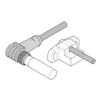
On the standard versions of the MiniCODER, the outer screen on the connec-
tion cable
● is connected to the MiniCODER housing
● is connected to the connector housing in metallised connectors
● is connected to a connector pin in plastic connectors
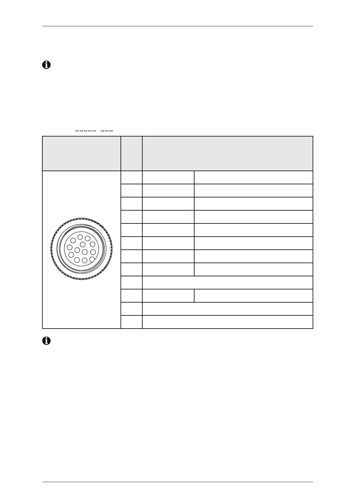
GEL 2444
J -
12-pin
male connector
(Mating view)
Pin Signal / function
1
2
3
4
5
6
7
8
9
10
11
12
1U
1+
Signal track 1
2U
1–
Inverse signal track 1
3U
N+
Signal reference track N
40 V GND
5U
B
+ 5 V supply voltage
6U
2+
Signal track 2
7U
2–
Inverse signal track 2
8U
N–
Inverse signal reference track N
9 Not used
10 U
Sense
5 V Sense
11 Not used
12 Not used
External sense regulation is required with long power supply cables!