Lenord+Bauer 6 Mounting and connectionPreparing mounting
GEL 2444 61
English
6.1 Preparing mounting
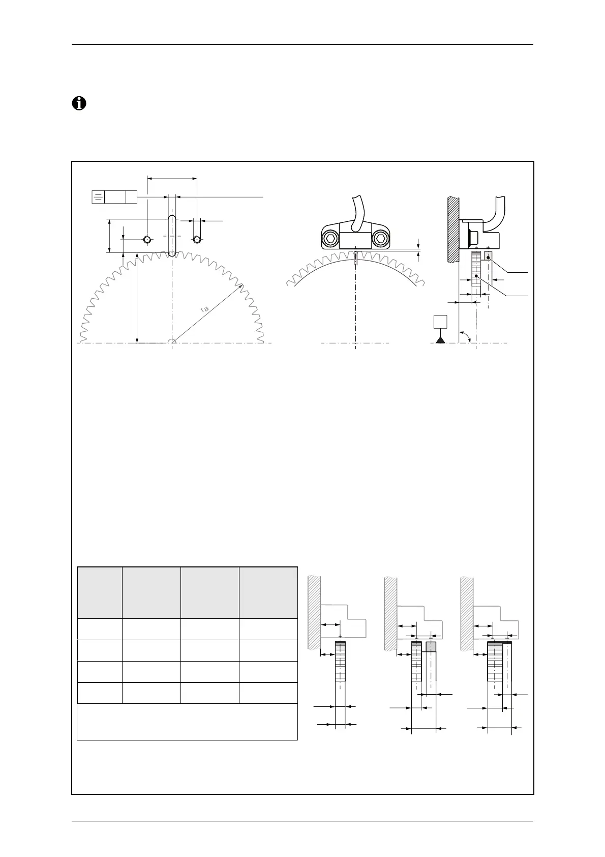
To ensure the correct function of the measuring system, MiniCODER and
target wheel must be exactly aligned and the tolerances met.
Hole pattern and installation dimensions
d
b
a
g
90°
± 5.7ʹ
T
Ref
T
Sig
A
A0.01
4 H7 (2 tief/deep)
27
± 0.1
18
7
M 4
r
a
- 1
All dimensions stated in mm
a Width of the signal track:
b
Mounting surface to tooth wheel distance: dependent on the geometry of the target
wheel
(for example, width of the signal track)
d Air gap: dependent on the module (see air gap table)
g Width of the target wheel
r
a
=d
a
/2 (with d
a
= Outside diameter of the tooth wheel)
T
Ref
Reference track
T
Sig
Signal track
Installation dimensions for standard
target wheels
Di-
men-
sion
ZA- ZAN ZAZ
g 4 10 10
a
1/2
446
a
N
-44
b 7.5 ± 0.5 7.5 ± 0.5 7.5 ± 0.5
Position of the sensor elements:
c
1
= ; c
2
=
All dimensions stated in millimeters
General tolerance ISO 2768 –mK
ZA- ZAN ZAZ
a
1/2
g
a
1/2
a
N
a
N
a
1/2
c
1
c
2
g
g
bb b
c
1
c
2
c
1