Electrical installation
Connection of motor / brake resistor
5
126
EDK82EV222 DE/EN/FR 13.0
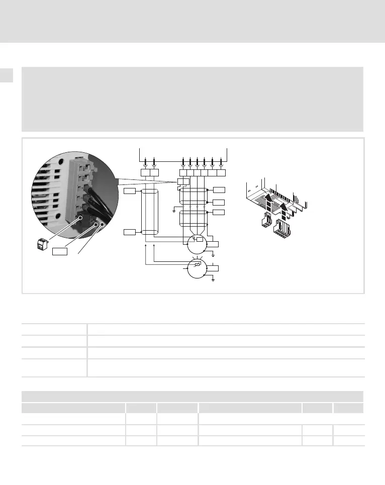
Connection of motor / brake resistor
Danger!
ƒ All control terminals only have basic insulation (single isolating distance) after
connecting a PTC thermistor or a thermal contact.
ƒ Protection against accidental contact in case of a defective isolating distance is only
guaranteed through external measures, e. g. double insulation.
1
2
X2.1
T2
T
1
X2.2
PE
PES
W V
U
BR2 BR1
PE
PE
PE
X2.1
PES
PES
PES
PES
T1 T2
M
3~
X2.2
ϑ>
PES
M
3~
PTC
8200 vector
}
PES
PES
PE
8200vec009
Use low−capacitance motor cables! (Core/core up to 1.5 mm
2
£ 75 pF/m; from 2.5 mm
2
£ 100 pF/m; core/shield
£ 150 pF/m). Motor cables that are as short as possible have a positive effect on the drive behaviour!
PES
HF shield termination through PE connection via shield clamp or EMC cable gland.
X2.1/PE Earthing of the 8200 vector at the output
X2.1/BR1, X2.1/BR2 Terminals of brake resistor
X2.2/T1, X2.2/T2 Terminals of motor temperature monitoring with PTC thermistor or thermal contact
Activate motor temperature monitoring with C0119 (e.g. C0119 = 1)!
Cable cross−sections U, V, W, PE
Type mm
2
AWG Type mm
2
AWG
E82xV251K2C / E82xV371K2C 1 18
E82xV551K2C / E82xV751K2C 1 18 E82xV551K4C / E82xV751K4C 1 18
E82xV152K2C / E82xV222K2C 1.5 16 E82xV152K4C / E82xV222K4C 1.5 16
 Loading...