Electrical installation
Supply voltage connection
4
51
EDBPM−H310 DE/EN/FR 7.1
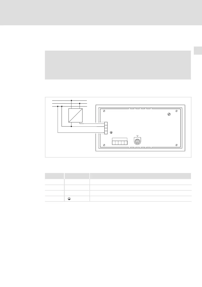
4 Electrical installation
Stop!
ƒ Damage of units connected. Connect the PE conductor as shown
in the figure!
ƒ Wire the operating unit only when no voltage is applied!
4.1 Supply voltage connection
LCD ADJ
+24 VDC
INPUT: 18 - 32 V 5W
FUSE 315 mA
0VDC
N.C.
ASP8
N.C.
CAN+
Shield
CAN-
V-
1
12345
2
3
4
PE
N
L1
~
–
+18...32VDC
h310_003
Fig. 4−1 Supply voltage connection
Terminal assignment
Terminal Identification Explanation
1 +24 VDC Supply voltage (DC +18 V ... 32 V)
2 0 VDC GND supply voltage, reference potential
3 n.c. Not connected
4 PE potential