Electrical installation
Wiring of the system bus (CAN)
4
52
EDBPM−H310 DE/EN/FR 7.1
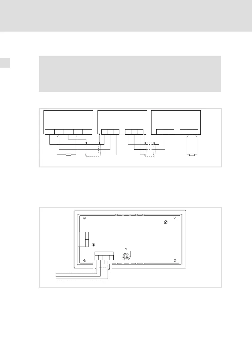
4.2 Wiring of the system bus (CAN)
Note!
ƒ Only connect terminals of the same signal type.
ƒ For further information with regard to the system bus (CAN)
please refer to the CAN Communication Manual.
Principle structure
ShieldCAN--V CAN+ N.C.
CG LO HI CG LO
CG LO HI
CG LO HI
HI
120
120
A
n
A
2
(H310)
A
1
h310_004
Fig. 4−2 Wiring of system bus (CAN)
A
1
Node 1
A
2
Node 2
A
n
Node n
Connection
LCD ADJ
+24 VDC
INPUT: 18 - 32 V 5W
FUSE 315 mA
0 VDC
N.C.
ASP8
N.C.
CAN+
Shield
CAN-
V-
1
12345
2
3
4
CAN-GND
CAN-LO
CAN-HI
h310_015
Fig. 4−3 System bus (CAN) connection