Installation électrique
Câblage du Bus Système CAN
4
84
EDBPM−H310 DE/EN/FR 7.1
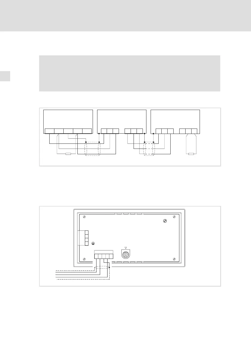
4.2 Câblage du Bus Système CAN
Remarque importante !
ƒ Ne relier que des bornes du même type.
ƒ Pour plus de détails concernant le Bus Système CAN, se reporter
au manuel de communication CAN.
Principe de câblage
ShieldCAN--V CAN+ N.C.
CG LO HI CG LO
CG LO HI
CG LO HI
HI
120
120
A
n
A
2
(H310)
A
1
h310_004
Fig.4−2 Câblage du Bus Système CAN
A
1
Participant au bus 1
A
2
Participant au bus 2
A
n
Participant au bus n
Raccordement
LCD ADJ
+24 VDC
INPUT: 18 - 32 V 5W
FUSE 315 mA
0 VDC
N.C.
ASP8
N.C.
CAN+
Shield
CAN-
V-
1
12345
2
3
4
CAN-GND
CAN-LO
CAN-HI
h310_015
Fig.4−3 Raccordement Bus Système CAN