More control
connecons
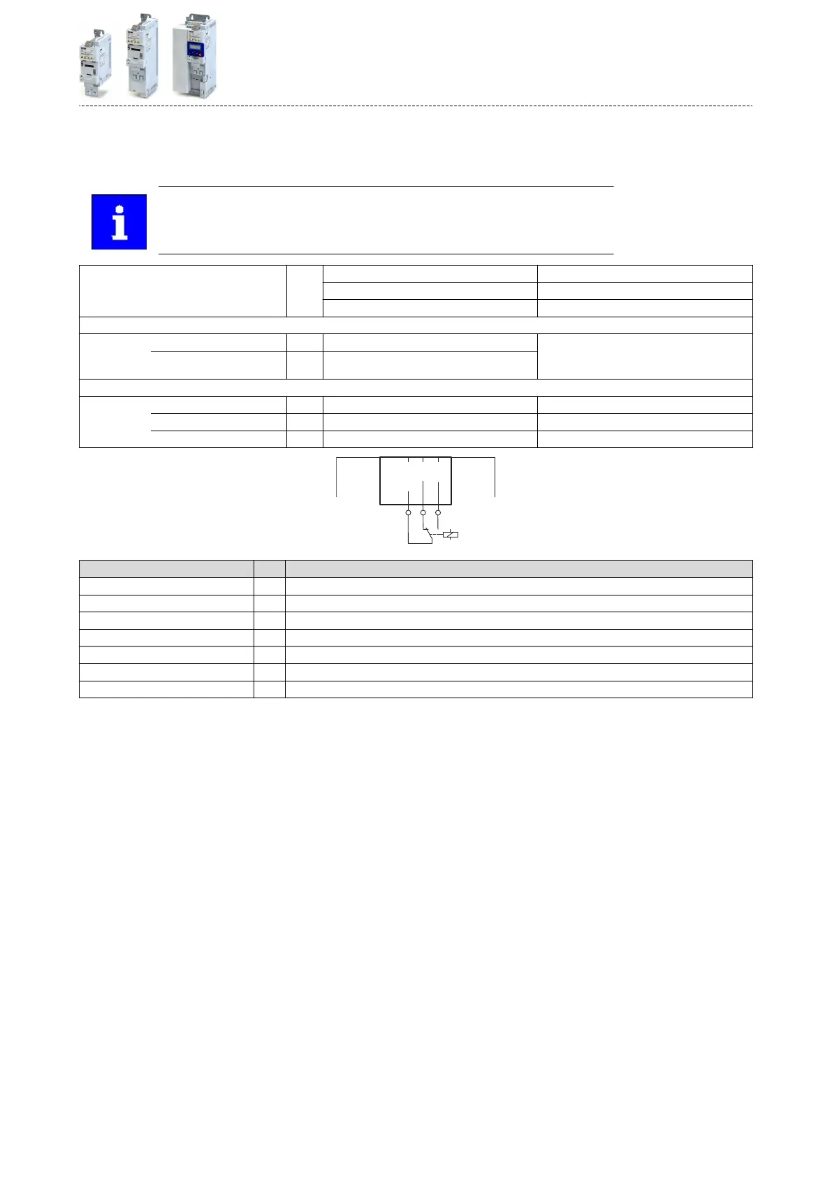
Relay output
Relay is not suitable for direct switching of a electromechanical holding brake!
Use a c
orresponding suppressor circuit in case of an inducve or capacive
load!
Connecon Terminal X9: COM Centre contact (common)
Terminal X9: NC Normally-closed contact
Terminal X9: NO Normally-open contact
Minimum DC contact load
Voltage V 10 A correct switching of the relay contacts
needs both values to be exceeded simultane-
ously.
Current mA 10
Switching voltage/switching current
Maximum
AC 240 V A 3 According to UL: General Purpose
DC 24 V A 2 According to UL: Resisve
DC 240 V A 0.16
Terminal
descripon Relay output
Connecon X9
Connecon type pluggable screw terminal
Min. cable cross-secon mm² 0.5
Max. cable cross-secon mm² 1.5
Stripping length mm 6
Tightening torque Nm 0.2
Required tool 0.4 x 2.5
Product extensions
Mor
e control connecons
Relay output
83

 Loading...


