Multi−axis controllers
General data and operating conditions
4
168
EDS94SPP101 EN 10.2
Design
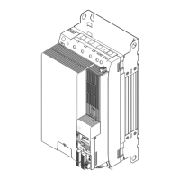
Housing
Carrier housing Device sizes
1, 2 and 3
Glass−fiber reinforced plastic
Carrier housing Device sizes
as of 6
Metal
Dimensions see "Mechanical installation"
Weight see "Mechanical installation"
Mounting conditions
Mounting place
in the control cabinet
Mounting position vertical
Clearance
above/beneath
Comply with the device−relating mounting instructions.
at the side
Can be installed in a row without any clearance
Supply conditions "Single Drive"
AC mains operation
No direct connection, DC supply module or "Single Drive"
network required
DC−bus operation Direct connection via terminals or busbars
For more information, please see the chapter DC−bus
operation.
Power systems
TT
Operation allowed without restrictions.
TN
IT Additional device−internal measure required (see ("Earthing
of internal EMC filters", 204)
Motors EN 60034 Only use motors that are suitable for inverter operation.
Insulation strength: max. û 1.5 kV, max. du/dt 5 kV/s
Operating conditions
Environmental conditions
Climate
Storage
IEC/EN 60721−3−1 1K3 (−25 ... +60 °C)
Transport IEC/EN 60721−3−2 2K3 (−25 ... +70 °C)
Operation IEC/EN 60721−3−3 3K3 (−10 ... +55 °C)
Current derating from +45 ... +55 °C: 2.5 %/°C
Site altitude 0 ... 4000 m amsl
1000 ... 4000 m amsl: current derating of 5 %/1000 m
Pollution EN 61800−5−1 Degree of pollution 2
Vibration resistance (9.81 m/s
2
= 1 g)
Transport
IEC/EN 60721−3−2 2M2
EN 61800−2
2 ... 9 Hz: Amplitude 3.5 mm
10 ... 200 Hz: acceleration resistant up to 10 m/s
2
200 ... 500 Hz: acceleration resistant up to 15 m/s
2
Operation
Germanischer Lloyd 5 ... 13.2 Hz: Amplitude ±1 mm
13.2 ... 100 Hz: acceleration resistant up to 0.7 g
IEC/EN 60068−2−6
10 ... 57 Hz: Amplitude 0.075 mm
57 ... 150 Hz: Acceleration resistant up to 1 g

 Loading...


