User Manual for BPS-2000
www.levitronix.com
PL-4021-00, Rev06, DCO# 21-037
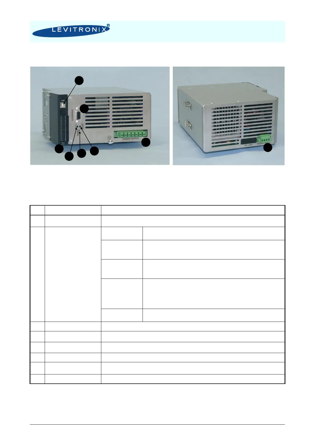
Figure 26: Overview of the controller LPC-2000.2-xx for extended operation
Position, field and temperature sensor signals from motor.
Torque spec. for tightening of connector flange screws on motor side: Typical 0.2 NM
- Analog current input: 4 – 20 mA
- 450 Ohm shunt input
- Analog voltage input 0 – 10 V
- Direct connection, no galvanic isolation
- 7.8 k input resistance
- Analog voltage output: 0 – 5 V
- Direct connection, no galvanic isolation
- Max. Output current: 2 mA
- Galvanic isolation with optocoupler
- Lowest input voltage for high level detection: min. 5 V
Typical 24 V / 16 mA, maximal 30 V / 20 mA
- Highest input voltage for low level detection: max. 0.8 V
- Minimum input resistance: R
IN
= 2.2 k
- Galvanic isolation with relay
- Relay: 1 A / 30 VDC, 0.3 A / 125 VAC
Drive and bearing currents of the motor.
1
Torque spec. for tightening of connector flange screws on motor side: Min. = 0.2 Nm, Max. = 0.3 Nm
AC power input
1
Torque spec. for tightening of connector flange screws on main cable: Min. = 0.2 Nm, Max. = 0.3 Nm
LED is on if supply voltage of signal electronics is present.
“Power Output not active”
Red LED
LED is off if the switched output stage of the controller is enabled. If the LED is on, the bearing
and drive coils of the motor carry no current.
Reset button of the controller stage.
Table 13: Description of interfaces of LPC-2000.2-xx controllers
Note 1: Connectors are not made for multiple connection cycles. Avoid connections cycles >25.