2.2 Standard System Configurations
2.2.1 Standalone System Configuration
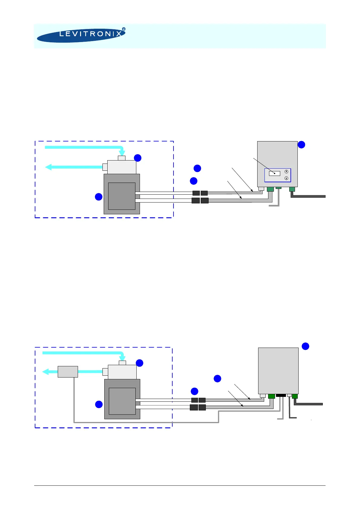
The standalone configuration of the BPS-2000 pump system (see Figure 3) consists of a controller with an
integrated user panel to set the speed manually. The speed is automatically stored in the internal EEPROM
of the controller. As an option, the speed can also be set with an analog signal.
Figure 3: System configuration for standalone operation
(Speed setting with integrated user panel)
2.2.2 Extended System Configuration
The extended version of the BPS-2000 pump system (Figure 4) consists of a controller with an extended
PLC interface. This allows setting the speed by an external signal (see Position 3b in Table 2) and enables
precise closed-loop flow or pressure control in connection with either a flow or a pressure sensor. A USB
interface allows communication with a PC in connection with the Levitronix
®
Service Software. Hence
parameterization, firmware updates and failure analysis are possible.
Figure 4: Extended operation (flow or pressure control) with extended controller
Controller
for
Standalone
Operation
Chemical Resistance and IP67 Space
Pump Head
Motor
Fluid In
Fluid Out
Motor Sensor Cable
Motor Power Cable
3 x AC 200-240V or
1 x AC 200-240V
Stand Alone
Operation
Speed Control
Adaptor/Extension
Cable for Sensors
Adaptor/Extension
Cable for Power
PLC Interface Speed Setting
- 1x Digital Input (Enable)
- 1x Digital Output (Status)
- 1x Analog Input (Speed)
Chemical Resistance
and IP67 Space
Controller
for
Extended
Operation
Pump Head
Motor
Fluid In
Fluid Out
Motor Sensor Cable
Motor Power Cable
USB
- Service
- Firmware Update
- Configuration etc.
Flow- or
Pressure
Sensor
Adaptor/Extension
Cable for Sensors
Adaptor/Extension
Cable for Power
Extended PLC Interface
Speed, Flow or Pressure Setting
- 4 Digital INputs, 4 Digital Outputs
- 4 Analog Inputs, 2 Analog Outputs
3 x AC 200-240 V or
1 x AC 200-240V